Sometimes you just need a project that you are trying to avoid to get you to work. For me, that has been a bathroom wall cabinet that I’ve designed and tweaked over the course of the past eight or so months. I’ve gotten advice about the joinery layout. I’ve selected and milled lumber for the case. I’ve pretty much committed to the build. And there the case parts sit next to my workbench. I can’t seem to get around to starting to cut dovetails.
That isn’t to say that I haven’t been working. Avoiding the bathroom cabinet project has motivated me to work on ramping up production of stock for my shop.
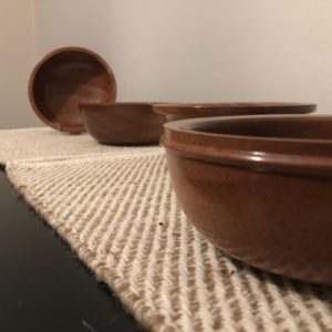
These sapele bowls each have an approximately 6″ diameter and stand 2.5″ tall. The two in back are a matched set. The one in front has an interesting beaded side, and the bowl that’s mostly hidden is an outside ogee.
I have new bowls to add to the shop, including a gorgeous spalted sycamore bowl and several sapele bowls.
While figuring out joinery for the bathroom cabinet, I built a small wall-hanging tea cabinet for the kitchen.
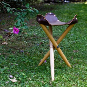
I even got around to finishing a camp stool that I had started a few years ago.
I don’t look at this as procrastination. The bathroom cabinet is not a high priority. Even if it was a higher priority, the planned details of the cabinet demand that time be taken on each step. I’ll get to it eventually. But, as you may have already guessed, it has to be placed on the back burner again. A few days ago I started a new run of sliding lid boxes.
One of the biggest hurdles to being able to do a craft show is not having enough stock of what I want to sell. When going to a show, you need to have enough pieces for people to browse through and enough to replace anything sold on your shelves or tables. I also would like to have a range of price points for people; you can’t sell an $800 Roorkee chair to everyone. What that means is being able to do small production runs.
This camp stool was turned from ash. The seat is a gorgeous brown leather.
Before Christmas last year, at the request of a friend, I experimented with a production run of headphone clamps in solid walnut. I ended up making eight of these, based solely on the lumber availability in the shop. The design I settled on for the product, and the level of finish that I wanted, meant that I spent a substantial amount of time on each unit. While these weren’t a loss in the end (and a few are still for sale), they aren’t suited to a reasonable batch process.
My small run of sliding lid boxes this spring was another experiment in production work. In the end, these boxes proved to be a more than reasonable balance of time and enjoyment to make. I combined hand and machine work. I even gave the new laser engraver a chance to shine. The boxes were well received, with four given as gifts and one retained as a recipe card box. Still, they were an iterative design. The first test I did was a small mitered box. I settled on doing rabbeted ends for the run due to machine limitations; my current table saw is simply not up to the degree of precision needed for making mitered boxes.* This iteration was fine for the short run, but not preferable. The rabbeting layout resulted in relatively fragile corners where the lid is pulled out.
So, taking stock of what I have learned, I am preparing to do another, much more substantial, run of boxes. These will find their way to a shop near you sometime soon. These boxes will be mitered, and likely have keys added for extra strength. Mitered corners do place a bit of a delay on the run, as I plan on using the new table saw for these cuts. I plan on adding some color details to the ends. Fabric-covered bottoms are also a consideration. I will also be adding decorative engravings to the front and back of each box with the laser engraver. And, I should be doing a total of 48 of these boxes, a significantly higher output than I’ve done for anything to date. The run was initially going to have 24 boxes. However, I believe the lumber being used is stable enough to handle resawing, doubling the output (and work involved). That said, this is a good lesson in small-batch woodworking.
In addition to these boxes, I’m working on refining the design of my turned kalimbas. I’ve had a chance to see how seasonal wood movement affects the tuning. I’ve also gotten a better feel for the minimum size of one of these as currently designed. I hope to do a run of these for sale some time before Christmas.
I also have a few small gift items planned, all things that can be done as relatively quick batch production, and all things that should have a low price point.
The bathroom wall cabinet will just have to wait.
* I have been working on a Ridgid R4513 jobsite saw for more than five years. It has been a constant battle. The table is not flat. The miter slot are not properly machined. The fence constantly goes out of square. Forget about easily beveling the blade. Even the handle to raise and lower the blade is junk. Still, I’ve gotten a lot of work done with the saw. But times, they are a-changin’. I was ready to take the plunge on a Sawstop contractor saw. Unfortunately two things stopped me, and it wasn’t the price. You can only get the Biesemeyer-style fence with the 36 or 52 inch rails. Given my shop layout and size, I can’t reasonably fit the saw width-wise into the shop. I did think about the fact that I could cut down the rails to better fit the space. However, the Sawstop contractor saw’s motor is mounted off the back of the machine, taking up additional space. In a 9×16 foot shop, every inch counts.
I ended up settling on the Laguna Fusion F1. Space-wise, it won’t take up any more width than the Ridgid job site. It is a bit deeper, but not to the degree that I’d lose significant space in the middle of the shop. I had thought about the F2. This suffers from the same width issue as the Sawstop. I could certainly cut the rails down, and would feel less bad about modifying it, but there was also an issue with availability. The F2 is looking at a December ship date. The F1 is available now. Regardless, this will be a huge upgrade for the shop. I look forward to a flat table and blade that can actually bevel without going cattywampus.
The weekend of September 6th, 7th, and 8th brought the annual Fair in the Park in Pittsburgh. For anyone unfamiliar with this event, it’s a three day arts fair put on by the Craftsmen’s Guild of Pittsburgh. The event features artists working in ceramics, fiber, glass, metal, jewelry, leather, and wood. Every year, the western Pennsylvania chapter of the American Association of Woodturners, Turners Anonymous, has a booth, not to sell, but to show work from members and demonstrate.
With Fridays free from the 9-5 job, I signed up to spend the day in the booth talking to folks and demonstrating. There were lots of wonderful folks that stopped by to talk art and woodworking, watch shavings fly on the lathe, and look at the works on display. I also had the chance to browse the wonderful artist booths throughout the park.
In preparation for the event, I wanted to put together a few example pieces to show what I would be demonstrating. I considered small items like pens and stoppers, as well as candle sticks/holders, bowls, and boxes. However, I decided that I wanted to try my hand at a musical instrument.
I remembered an old episode of the Woodwright’s Shop from the 1980’s where Roy looked at different traditional African instruments. One of the instruments, a mbira or kalimba, could be as simple as a board with metal or wooden tines set to be able to vibrate. Adding a resonating chamber to the board helped amplify the sound. So, if a box is all that was needed, why not a turned box? I obtained a tines and bridge hardware and set about trying to figure out the size for the turning.
Kalimba #1 was made out of cherry and ended up a bit small. Additionally, the kit that I had obtained contained one inch screws, suggesting a need for a rather thick sound board. This first box was made with that in mind. The result is a much smaller resonating chamber and a quieter instrument.
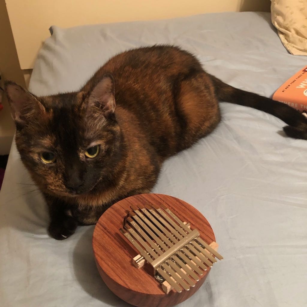
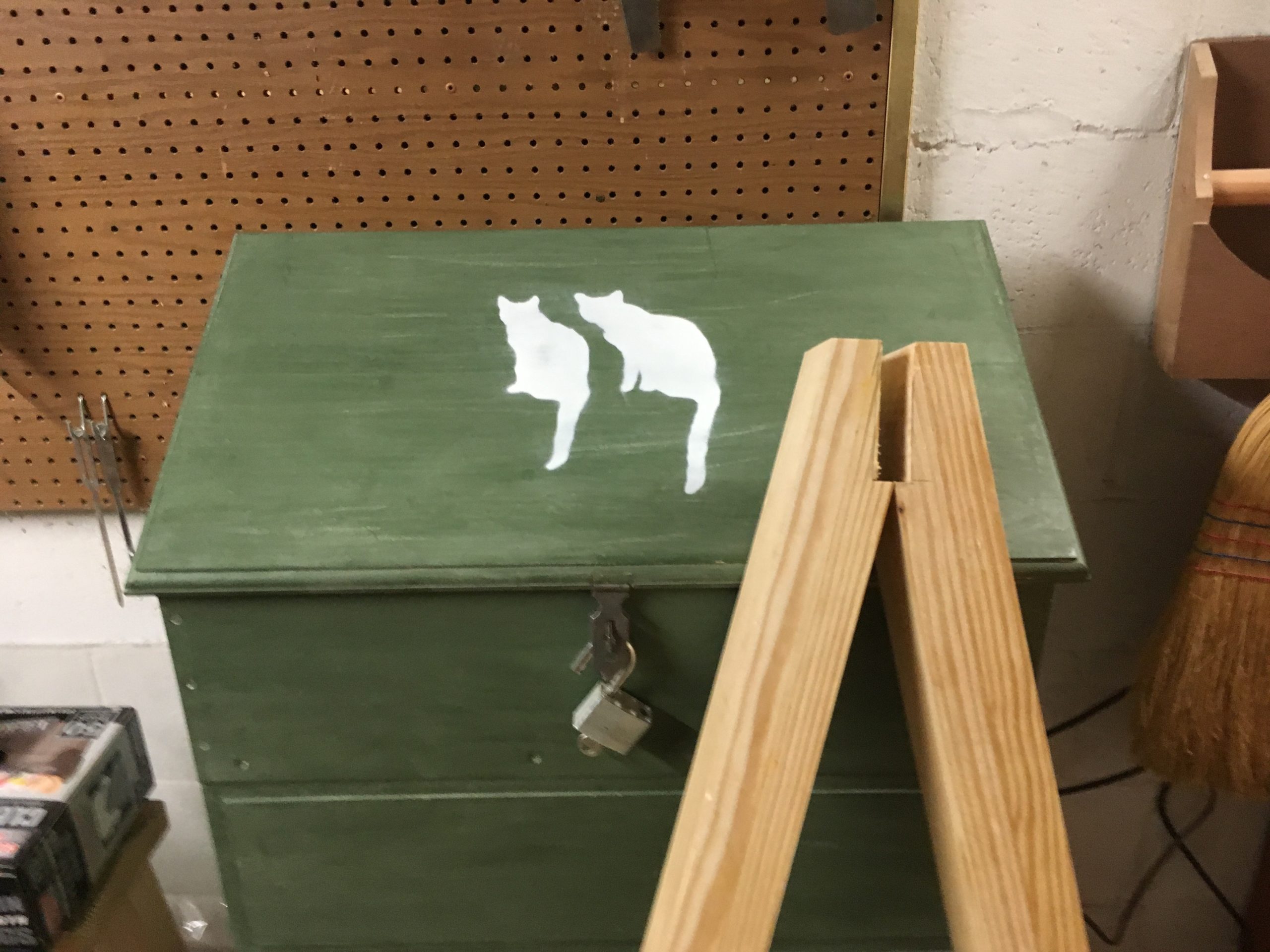
Ruby the Cat posing with Kalimba #2
Kalimba #2 was made from Hormigo (also called Orange Agate, Macacauba, or Macawood), a central american hardwood. I’ve worked with this wood several times before and find it to be easy to turn. It also accepts a very nice finish. The sound board was made significantly thinner. Due to the initial size of the blank, I was left with a relatively small instrument that could only accept nine keys. It has a very nice sound and handles very well.
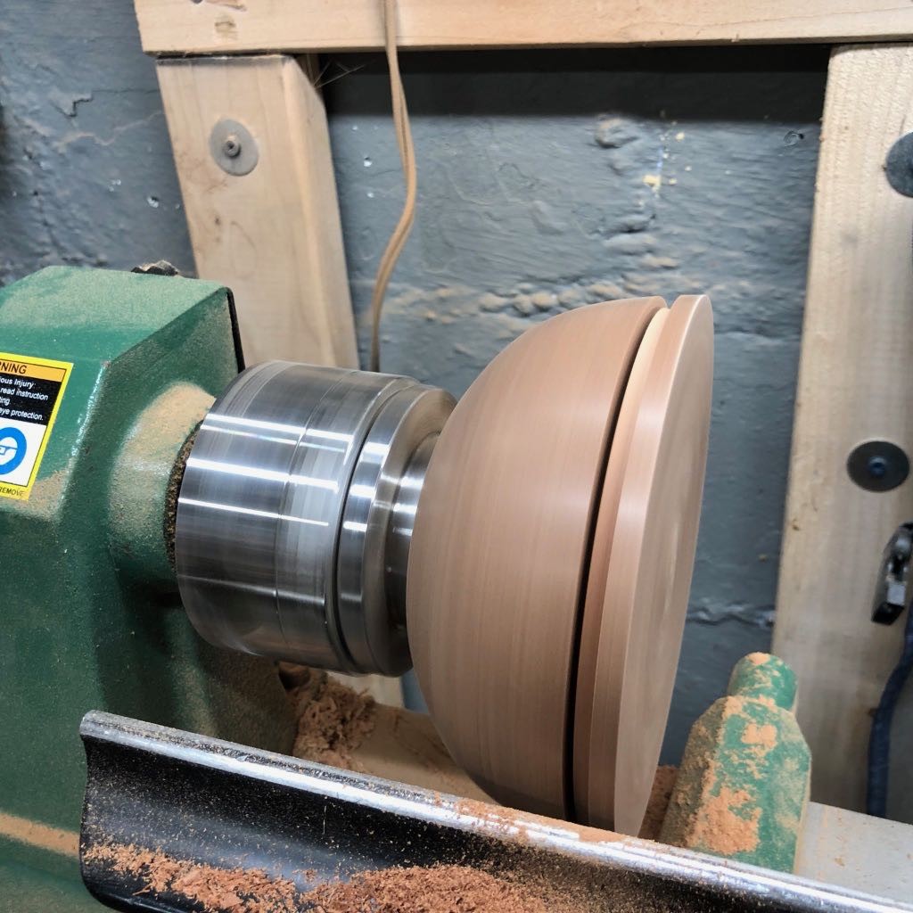
On the first day of Fair in the Park, I had an opportuntiy to demonstrate the making of the instrument. The process is fairly straight forward for anyone that has turned a lidded box before. After placing a bowl blank between centers, I turned down the blank, shaping the outside of the bowl and adding a tenon to the foot to allow the bowl to be placed into a four-jaw chuck. Once the outside was turned and sanded, the bowl is reversed placed into the chuck. The top of the blank is then flattened, taking care to remove any piercing from the spur center. Once the top is flattened, a lip is turned into the top where it will be fitted to the bowl. After the lip is established, the top is parted off. The cherry blank used for Kalimba #3 was larger than #1 or #2 and I did not have my handsaw with me. This made parting off a bit of a chore.
After the top is parted off, the next step is to start hollowing the bowl, taking care to establish the side walls so that the top will fit snuggly. Once the walls are established, the rest of the bowl can be hollowed out and sanded. Finish, if desired, should be applied to the inside of the bowl at this point.
Once the bowl is finished, the top inside lip of the top is coated with an epoxy and fitted to the bowl. After giving the epoxy time to set, I then cleaned up the transition between the bowl and the lid. The lid is then flattened, the sound hole drilled, and pilot holes for the screws for the grounding bar are also drilled at this point. The entire bowl can then be removed, flipped around, and placed in cole jaws to remove the tenon and clean up the bottom. Final finishing can then be applied. After the finish is cured, the grounding bar, bridge, and tines can be added, and the instrument given its first tuning.
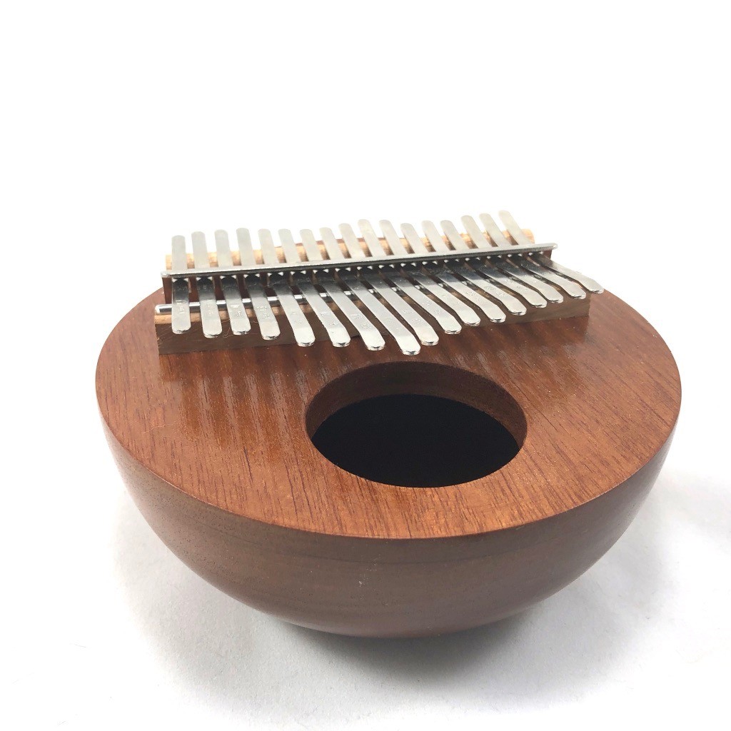
17 Key Cherry Kalimba
Kalimba #3 was made from cherry. The top was made significantly thinner and the bowl much thinner, resulting in a larger resonating chamber. The sound quality remained clear with the ability to amplify sound much better.
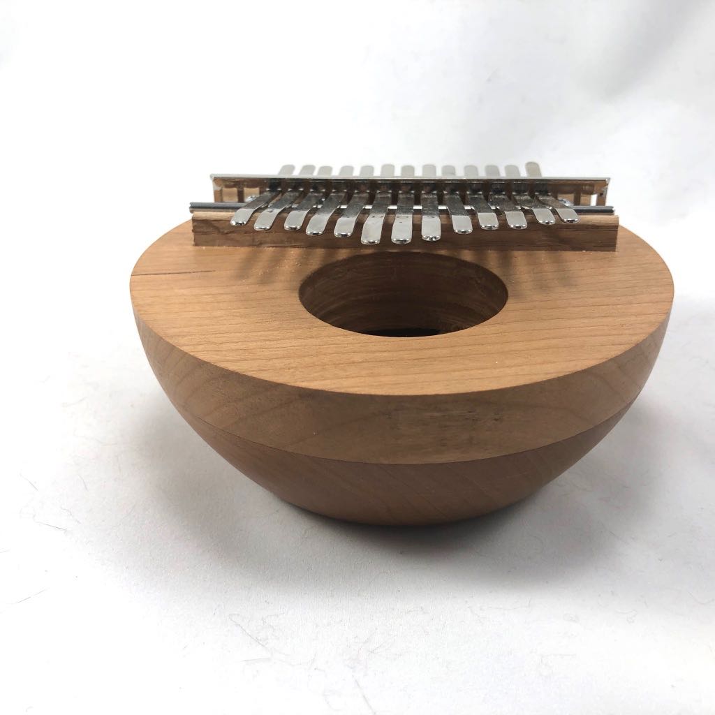
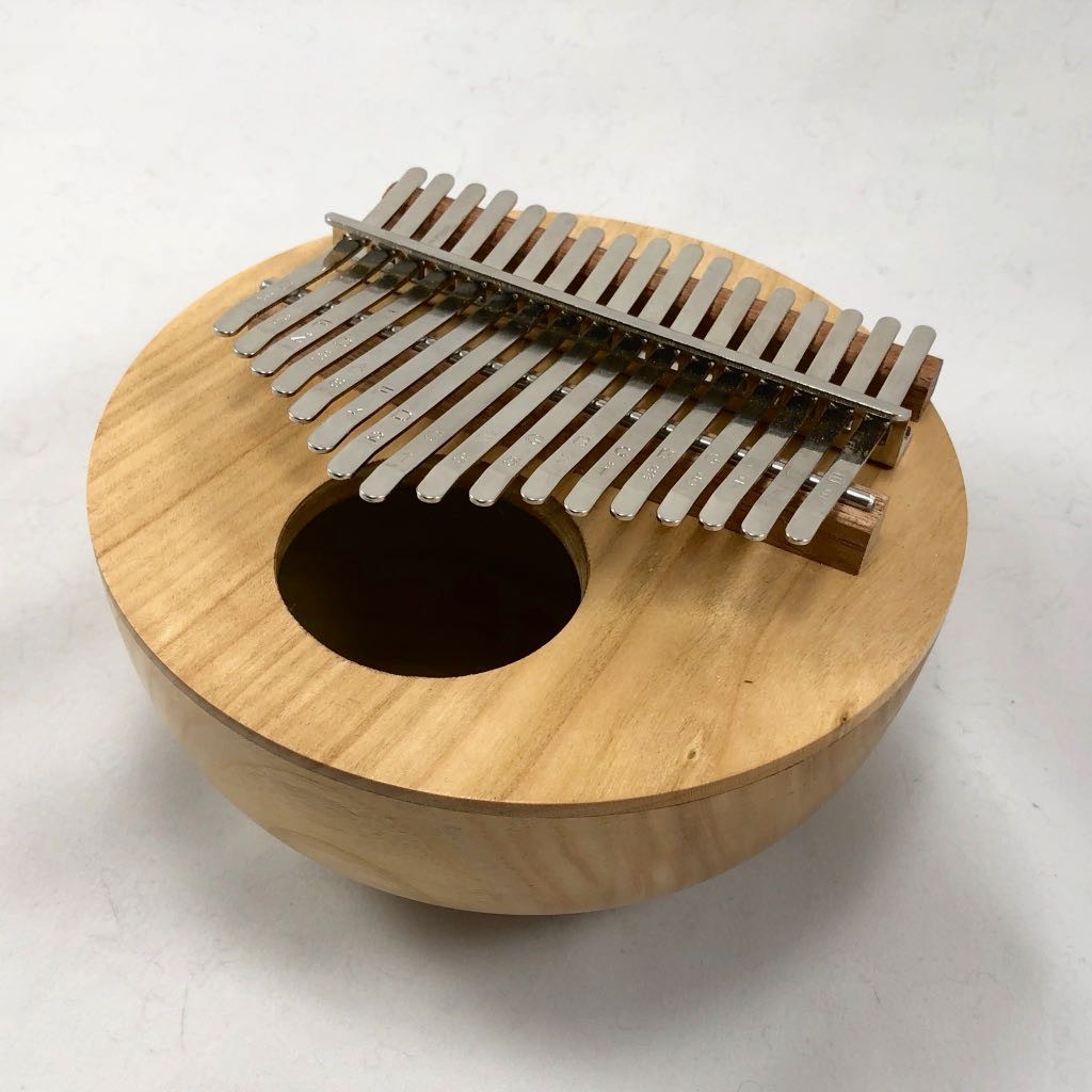
17-Key Sapele Kalimba
Kalimba #4 was made from sapele. The initial process for this was the same as the prior three instruments. However, I wanted to obtain a perfect grain match. The sound boards for kalimbas #1-3 were each made by flattening the top of the intact bowl, creating a lip on the outside of the bowl, and then parting off the top. The top was then flipped over and placed into the hollowed bowl. This resulted in an inability to get a perfect grain match.
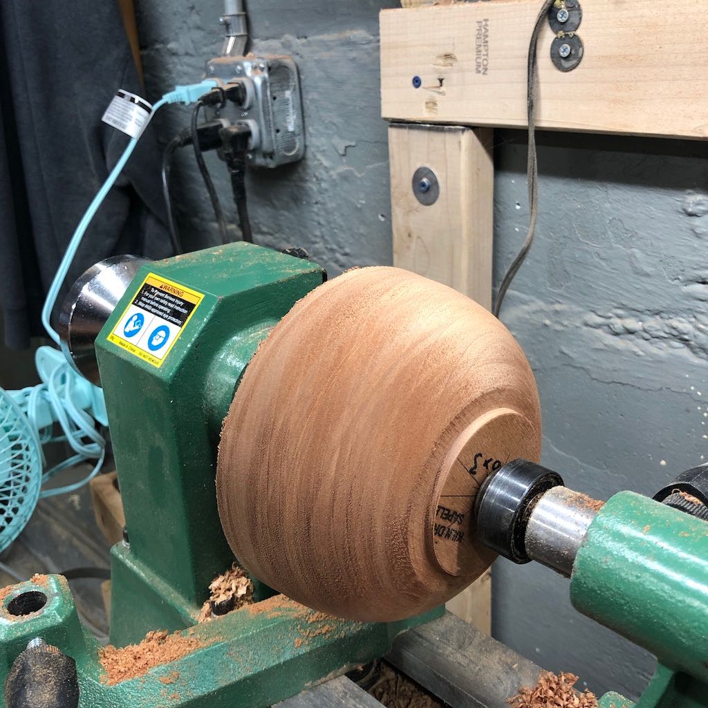
The blank is place between centers. A tenon is turned into the base and the outside of the instrument is roughly shaped.
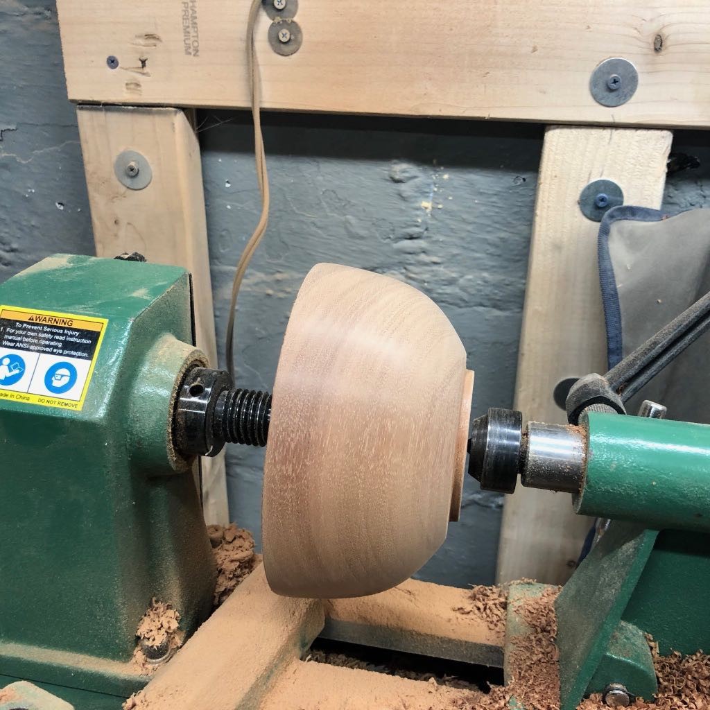
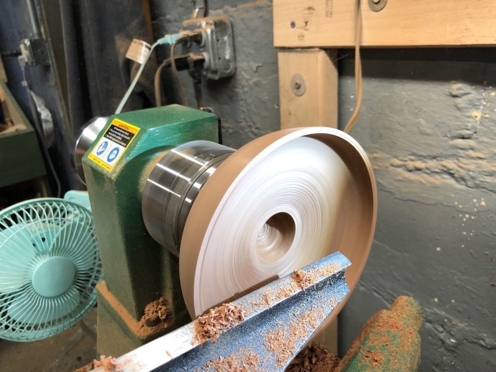
The final shape of the outside curve is established, including sanding up to 600 grit.
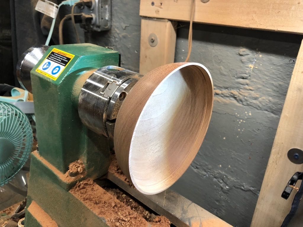
The bowl is turned around and placed in a 4-jaw chuck. The top is then flattened. A lip is turned and then the top is parted off.
With the top parted off, a lip to accept the top is established and hollowing can begin.
Checking the bowl thickness and depth is important at this step. Once the bowl is hollowed, it can be sanded down.
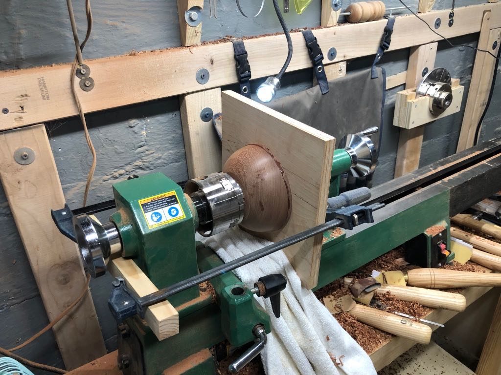
Epoxy is place around in inside of the lip and the two sides are fitted together. I used a piece of plywood pushed by the tail stock to apply clamping pressure.
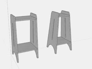
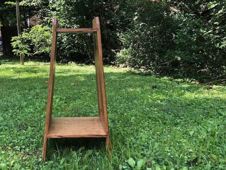
This project started based on a request for a small stand to hold a vase. I initially started to consider building a small Shaker-style side table. However, I had a few pieces of red oak in my lumber rack which were calling out to build something in the Arts and Crafts style.
The Design
Straight vs. Splayed Sides in SketchUp
The plan for the stand involved sides would taper in width from bottom top. I had initially considered using straight sides with tapers. However, working with SketchUp allowed me to play with adding splay to the sides that both sloped inward toward and tapered in width from bottom to top. The sides would have arrow-point piercings and arches to define feet.
Build Process
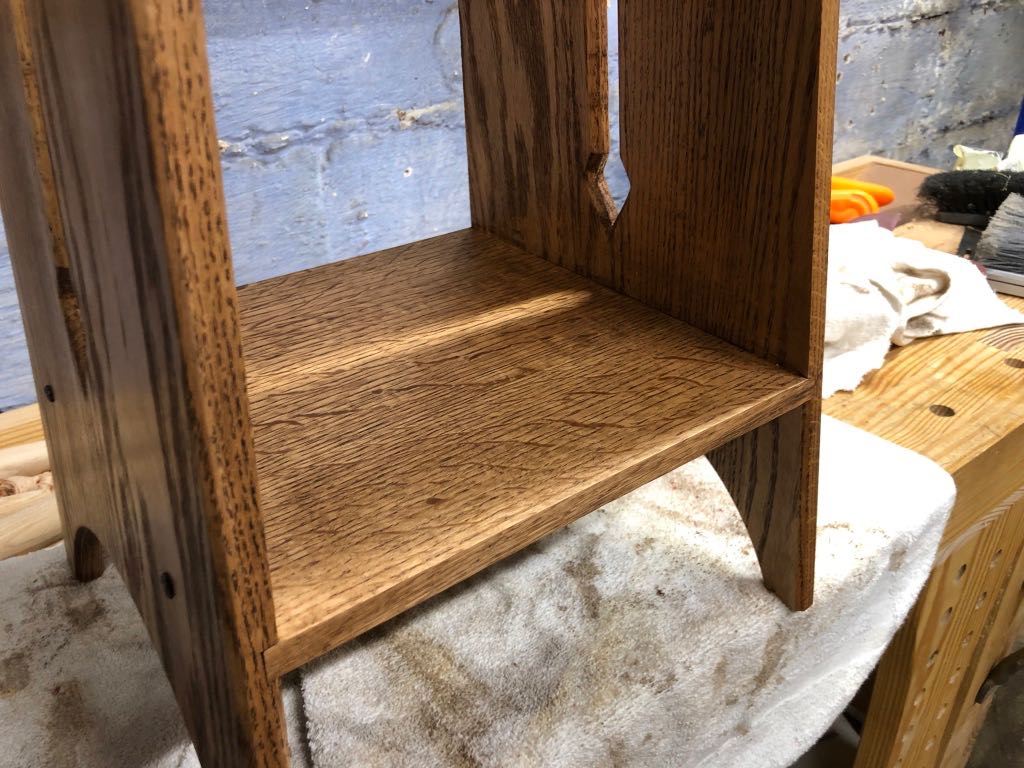
The piece as fairly straight forward to build, with the only “trick” being to save tapering the sides until last. Oak panels were glued up to reach the maximum width on the bottom of 13 inches and length of 28 inches. The sides ended up 5/8″ thick. Two shelves were glued up, with the bottom shelf measuring about 12 1/4″ wide and 13″ long, and the top measuring 9 3/8″ wide by 10″ long. These were 1/2″ thick.
Once the sides were glued up, flattened, and squared, I set the table saw to a 5º bevel and beveled the top and bottom edge of each side to match the intended 5º splay of the legs. I then swapped out my combo blade for a 1/2″ dado stack, leaving the 5º bevel setting intact. Dados were then cut into the sides for both the top and bottom shelves on each side.
Quartersawn Red Oak Shelves held in place with dados and rosehead nails.
After the dados were cut, the combo blade was swapped back into the saw, leaving the 5º bevel. I then began the process of trimming the ends of each self to the proper length. The bottom shelf was trimmed first, maintaining a length as close to 13 inches as possible. One end of the top shelf was then beveled. The stand was partially assembled with the bottom shelf in place. The top shelf was then aligned (but not inserted as it was still too long), and the unbeveled end was marked to find the final length. This was a tedious process and I’m considering a better way to do this going forward.
Before tapering the sides of the stand, I turned my attention to the arrow point piercings. These piercings involved up and down arrow points connected with a 1/2″ channel. I started by creating a template of the arrow point shape. The template was then used to draw the arrow points in both top and bottom locations, centered on the 1/2″ channel. With a Forstner bit, I removed the bulk of the waste in each point. I then pulled out a router with fence and spiral upcut bit installed. Setting the fence on the router to dead center of the sides, I then routed out the channels in each side. I returned to the arrows with chisels, cutting to the lines and defining the full arrow. Then, with a chamfer bit installed in the router, I routed around the piercing. This was finished with a chisel and knife to reestablish the points at the very top of each arrowhead, leaving the sides rounded.
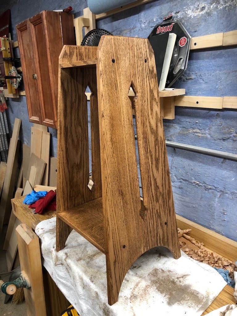
After the piercings were complete, each side was then tapered 5º from bottom to top using the band saw, cleaning up the marks with a jointer plane. I then measured and marked in from the top corner 3/4″. Using a bevel gauge set to match the angle of the arrow points, I marked a line and cut the final bevels. the outside edges of both sides where then chamfered with the router.
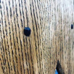
Wrought rosehead nails to add decoration and strength to the shelves.
The piece was then dry fit to allow for marking each shelf’s final depth. These were then ripped down on the table saw and cleaned up with hand planes to match the taper of the sides. The stand was glued up and finished using a wash coat of shellac, followed by a dark walnut stain, and topped with black paste wax. Wrought rosehead nails were then put through the sides into each shelf.
Thoughts for the Next Batch
There were a few mistakes along the way in execution of the design. First, I would prefer to make the next round entirely out of quartersawn stock. I had only enough quartersawn oak for the shelves. The sides were glued up out of the remaining stock which was mostly flat sawn. I didn’t notice until the piece was in the finishing stage, but I should have flipped one of the sides to align the flat sawn pieces. The panel glue up was also somewhat glue starved, as I found when inserting tight shelves. It resulted in a partial glue joint failure. This was remedied by wicking in some hide glue, but I’d rather not have to deal with this mid-build.
Second, if making the piece again, I’d likely make a full template of the sides and piercings to allow for template routing. Roughing out tapers on the band saw and cleaning it all up with a flush trim bit would save significant time over repeated resetting of the table saw, particularly given the jobsite saw that I work with.
Finally, I’d need to consider a better method to size and trim the shelves. What that method is I’m not yet sure.
Apologies in advance as this will be a photo-heavy post.
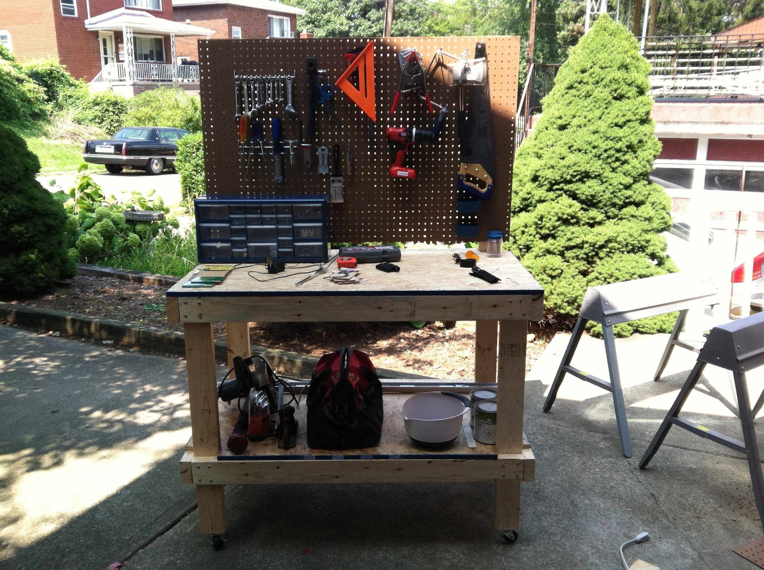
My First Workbench
Since moving into our current house about five years ago, I have been working on a small workbench built out of 2x4s and OSB. The work surface measured 4 feet by 30 inches. It also had four casters fixed to the feet. This had started out as a general workbench, not something woodworking focused.
Eventually, I lopped off the pegboard back and added a face vise. This bench then served as my primary bench for all woodworking, which is to say, it mainly held my lathe, which could be pushed out of the way when I needed the front half of the bench.
In addition to turning, I managed to complete a few other projects, including a shaker candle stand, cabinets, and picture frames. However, with a thin OSB top, lack of squareness, lack of work holding for face work, and poor front vise setup, the bench has been poorly suited building new hand tool skills. Additionally, at four feet long, I was unable to support my lathe with a bed extension. That meant I haven’t been able to turn more than 18 inches between centers, precluding turning chair spindles.
Time For A Change – Figuring Out What To Build
Once I decided to build a new bench, the first task at hand was to read and watch as much as I could about workbench design. I started by reading Workbenches (from Design & Theory to Construction & Use) from Chris Schwarz. If you’re even dreaming about building a workbench, this is a great place to start. While plans are included for a few different bench styles, the discussion about the why of design choices is even more informative. That said, when I got down to the actual build, I would turn to the book to answer questions like “just how high should the stretcher between the front legs be?”
Other written sources included online plans for benches, blog posts, and articles in both Popular Woodworking and Fine Woodworking.
In addition, I watched a number of YouTube videos, including Paul Sellers bench build series. I also watched a couple of episodes of The Woodwright’s Shop, including an early episode (in Season 3 of the show!)
and a pain of episodes recreating a French workbench with a narrow top, splayed rear legs, and tool well. I’ve seen both Part I and Part II of this build a couple of times on PBS and was a fan of the general design.
Settling on a Design
After too much reading and watching, I knew a couple of things:
I wanted a bench that is between five and six feet long.
I want a bench no deeper than about 22 inches.
The new bench needs to be heavy.
It needs a thick top (for heft)
It needs to be solid.
With that in mind, I started to design a bench in the Roubo-style, made out of laminated SYP. Firing up Sketchup, I started making laminations and put together an initial idea. It consisted of 15 laminations of ripped down 2×12 stock for a final width of about 22 inches. Four legs would be laminated and mortised into the top, each with a double tenon. A leg vise would be added to the front left leg and I would install my Yost quick release vise on the right side as a tail vise.
That is about as far as I made it with this design. I never got around to adding in stretchers, shelves, or figuring out a dog or holdfast arrangement.
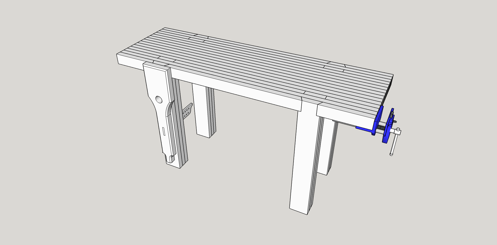
As I noted above, I was a fan of the French Bench design demonstrated by Roy Underhill. As much as I liked that design, he used a sliding dovetail for both the front legs and rear, splayed, legs, that seemed (and still does seem) a bit too intimidating for my current skill set. I figured that I wouldn’t be able to use splay-leg design as a result. However, I came across a great piece written by Jim McConnell on his blog The Daily Skep. In The Student Bench Takes Shape, he detailed building a couple small benches for use by students learning hand tool work. His design for the benches featured a narrow top, front legs mortised into the bench, and splayed rear legs. Instead of using a sliding dovetail to attach the rear legs, he cut a birdsbeak and drove screws through the leg and into the top.
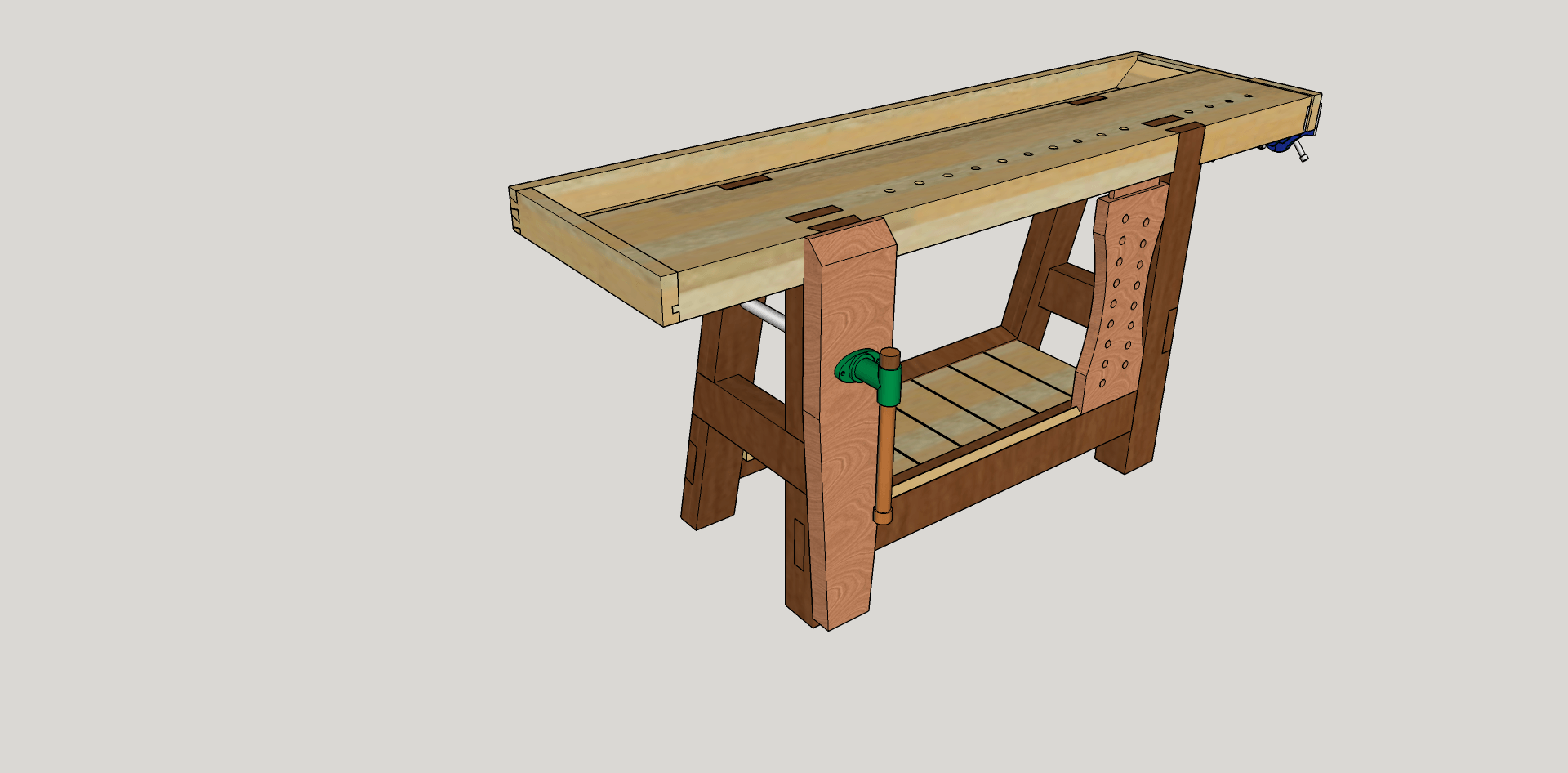
The birdsbeak, with a matching notch cut into the benchtop, was the solution to my hang-up with Roy’s French Bench design. I went back to SketchUp and put together a new design. The front legs are still joined with a double tenon. However, the back legs are now splayed and given a birdsbeak with notches cut into the benchtop. Additionally, I brought the width down to about 12 1/2″, with a tool well that is approximately six inches wide. The total designed width comes in at just under 22 inches. The top is about 3 1/2″ thick. I also added a sliding deadman and a shelf. A leg vise remains at the front left and the quick release vise continues to act as a tail vise.
Building the New Bench
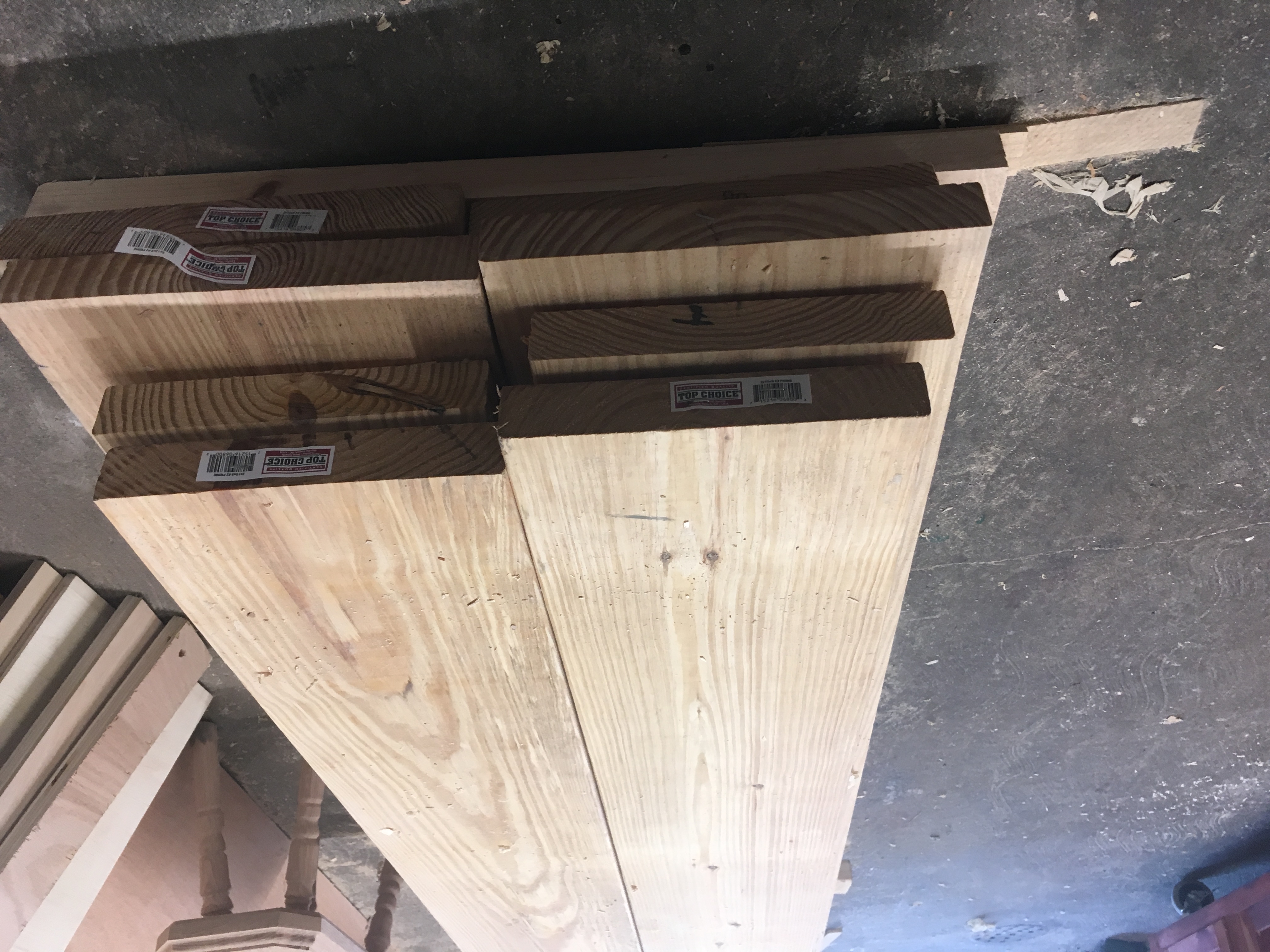
With the design locked in, I figured out a cut list and it was off to buy some lumber. Since the back half of the bench would be a tool well, and the front half would be narrow, I significantly cut down on my lumber needs. I purchased four 2×10 and four 2×12 eight-foot lengths of SVP in early April. When I got them home they went into the garage and were stickered with the intention of starting on the bench after waiting another two weeks.
Preparing the Lumber
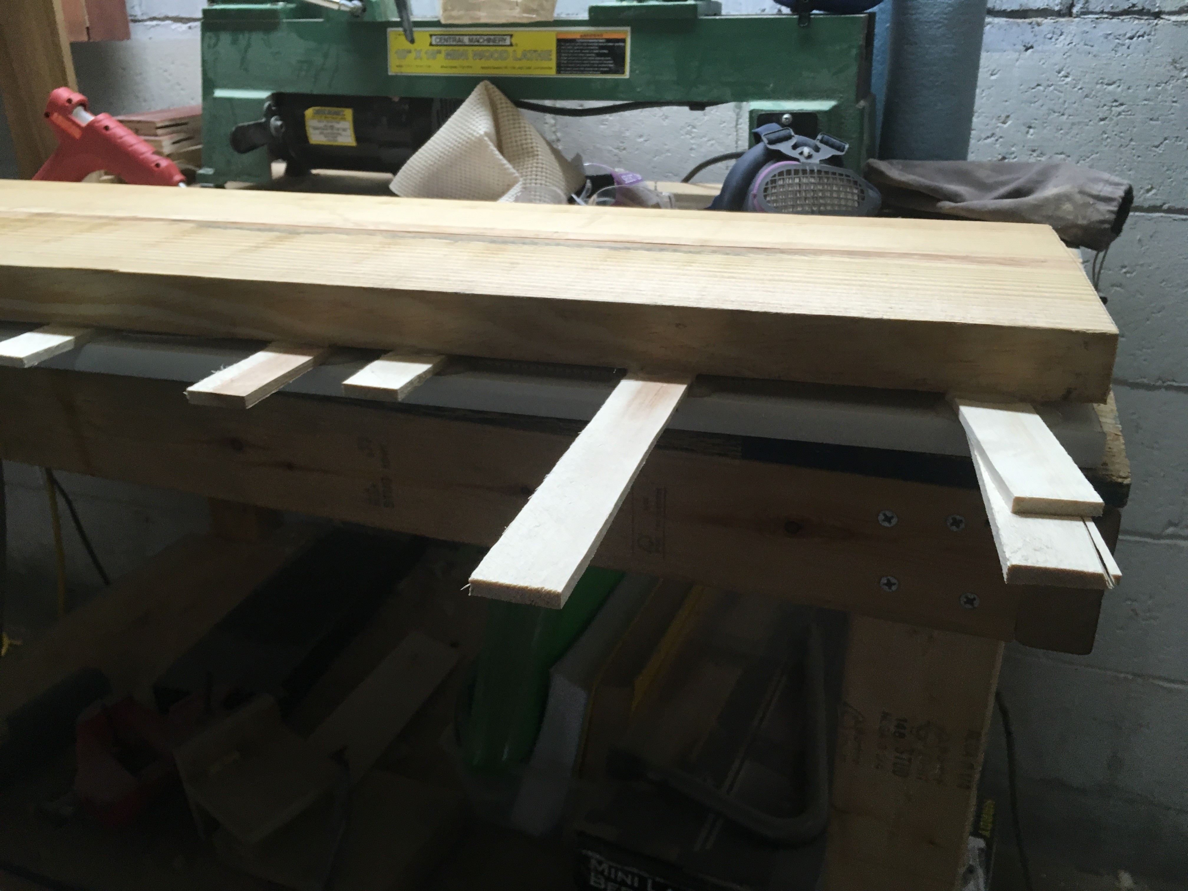
Due to recurrent back problems, I had to wait nearly two months before returning to the workshop. When I did go back to the shop, I found that the lumber had generally behaved well. However, it all needed to be jointed and thicknessed due to twist and bowing in most pieces. Since I don’t have a jointer, I put together a six-foot jointer sled for my thickness planer. The time involved in setting up each piece of lumber, including gluing shims, cutting them down, and praying the glue holds to the melamine have convinced me that I should keep my eye out for a nice used jointer.
Laminating Parts
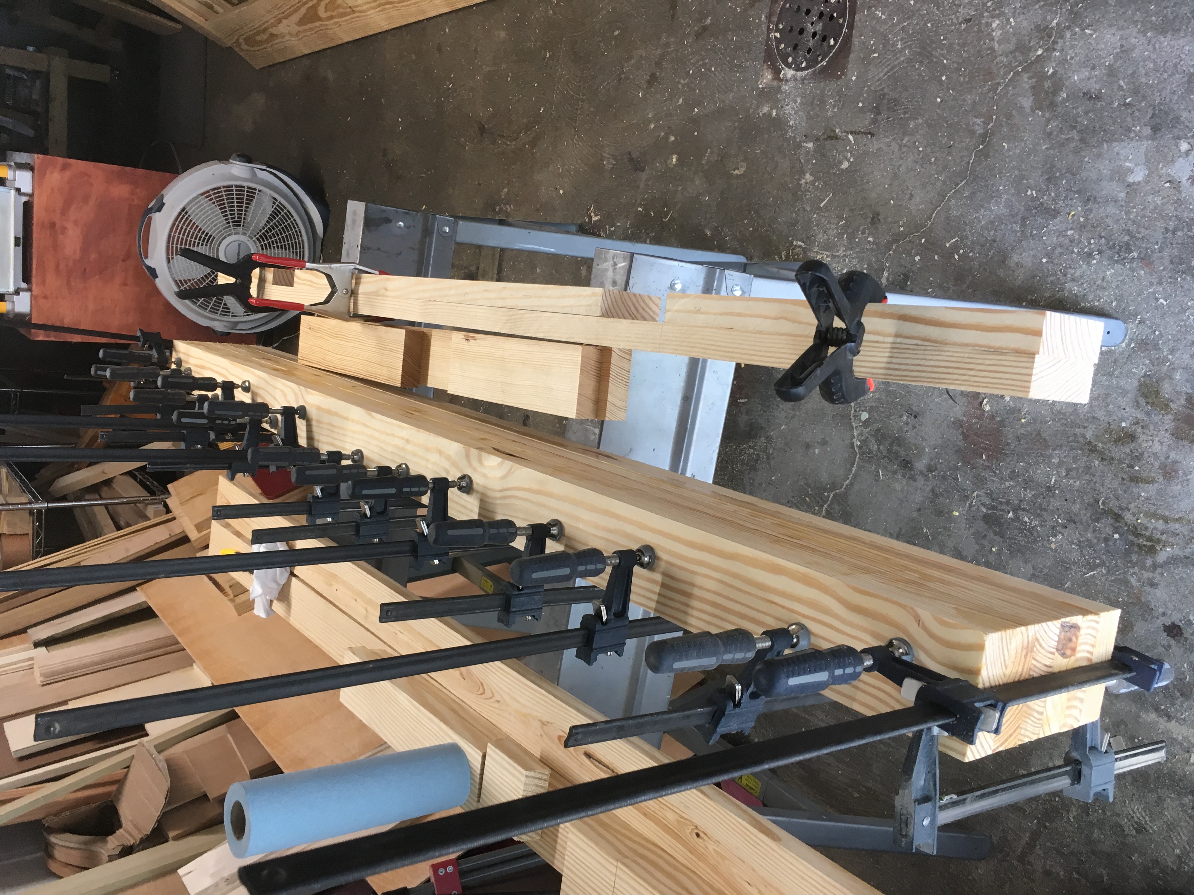
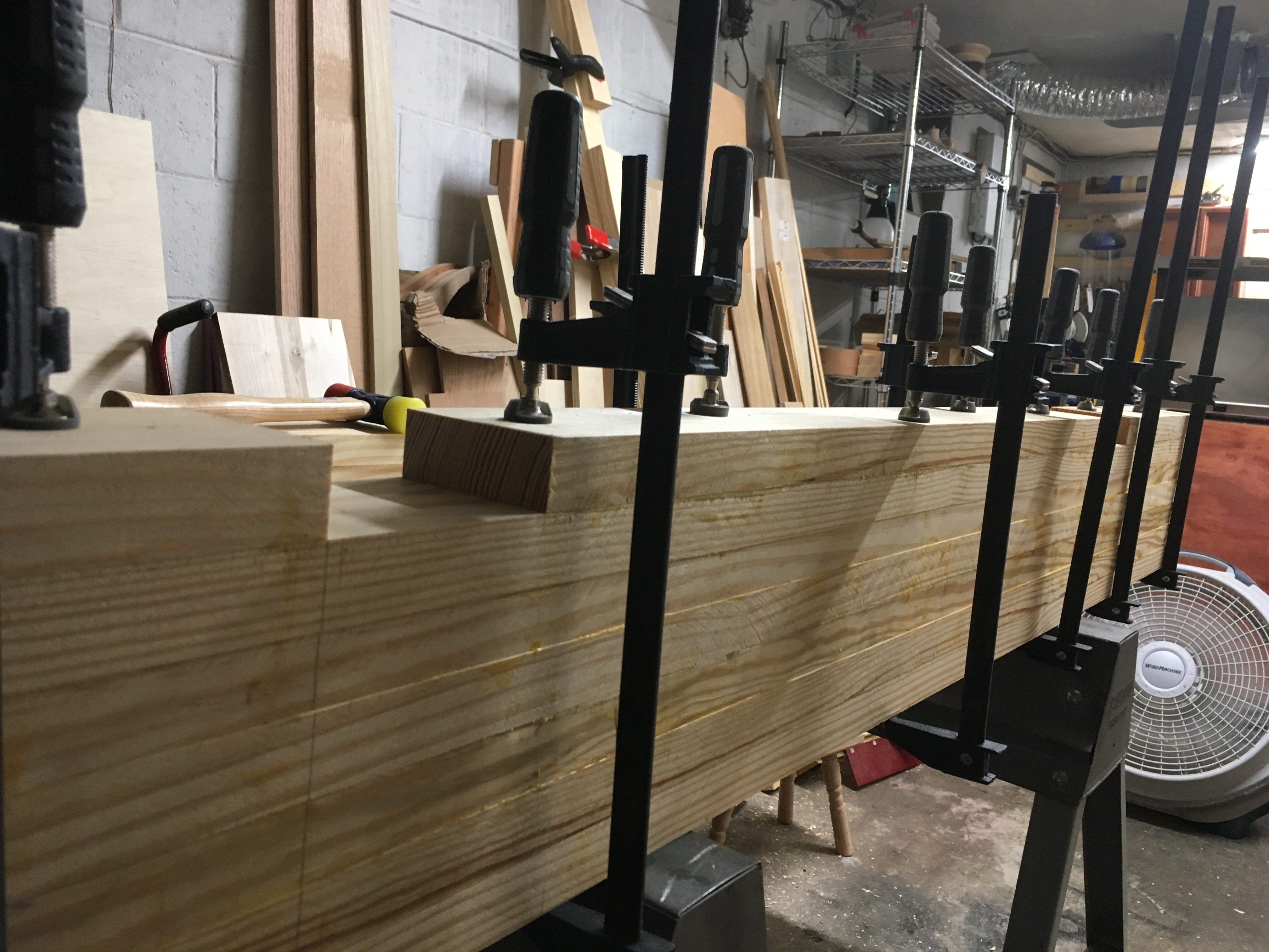
With everything jointed and thicknessed to 1 1/4″ inches I was able to start the lamination process. I had thought about using biscuits to help with alignment but decided against it. In retrospect, it would have made things much easier. Working on a set of steel sawhorses that I’ve had since moving into the house, I laminated the center section of the benchtop, about six laminations, in one go.
Despite my best efforts (or, mediocre efforts if we’re being honest), I ended up with some vertical misalignment between each lamination. While I was able to correct it later, it meant sacrificing a little bit of thickness in the top). I’m going to put part of this down to having waited a few days between ripping and thicknessing material and moving on to glueup. Even with nearly two months in my garage, the SYP is still wet and had movement in it. Lesson learned: mill your stock and glue it up the same day.
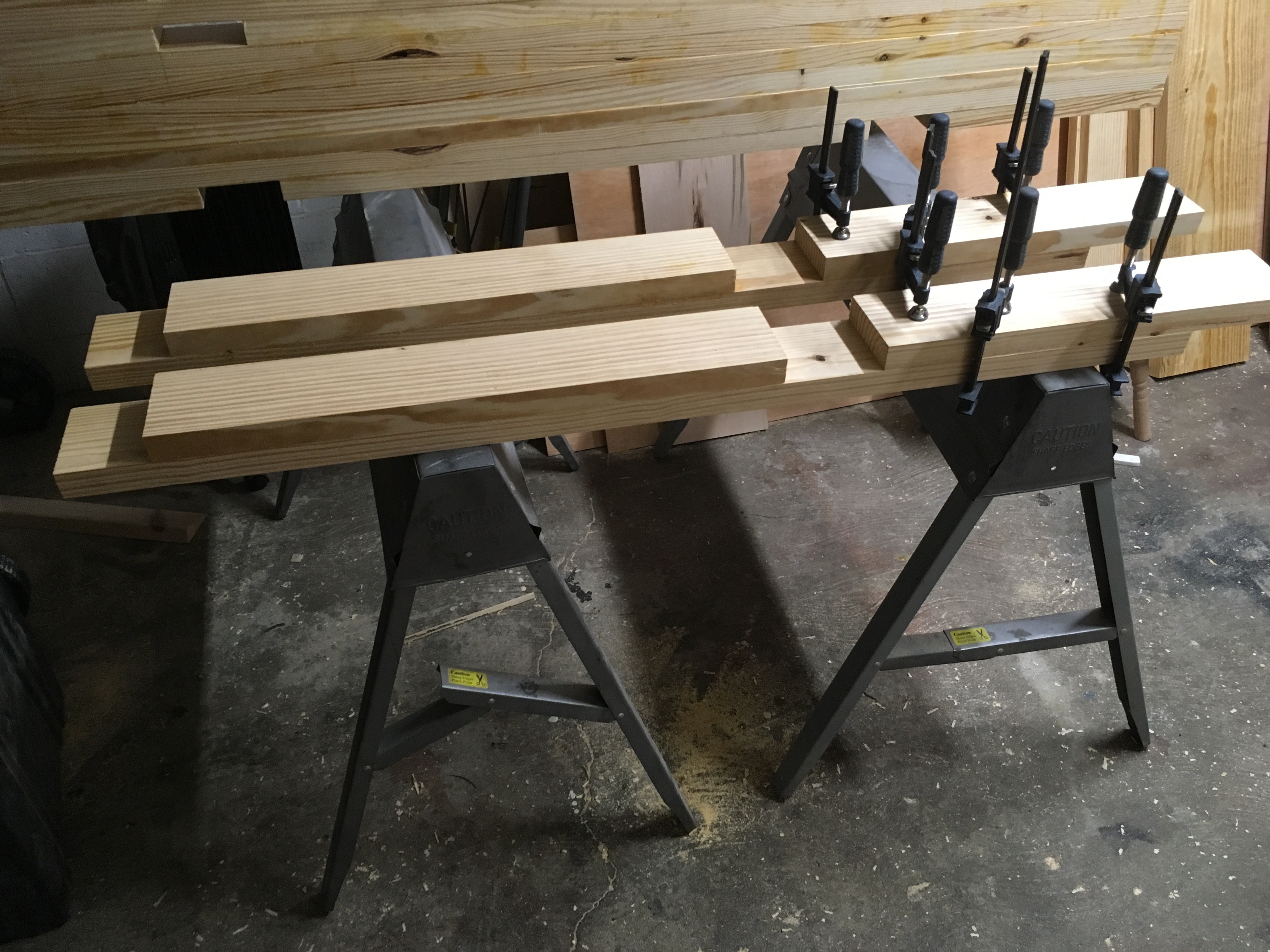
After getting the center section glued up, I went on to the front three laminations. Each of these was precut to fit the leg tenons, including precutting the dovetails mortise for the front tenon. The notches for the rear legs were also precut and glued up in a similar manner.
With the benchtop glued up, I went ahead and cut and glued up both the front and rear legs. The front legs consisted of a three-board thick lamination, with a precut mortise for the front stretcher. The rear legs are two boards thick. Additionally, the front legs have the tenons pre-made by gluing them up about 3.5″ above the middle section.
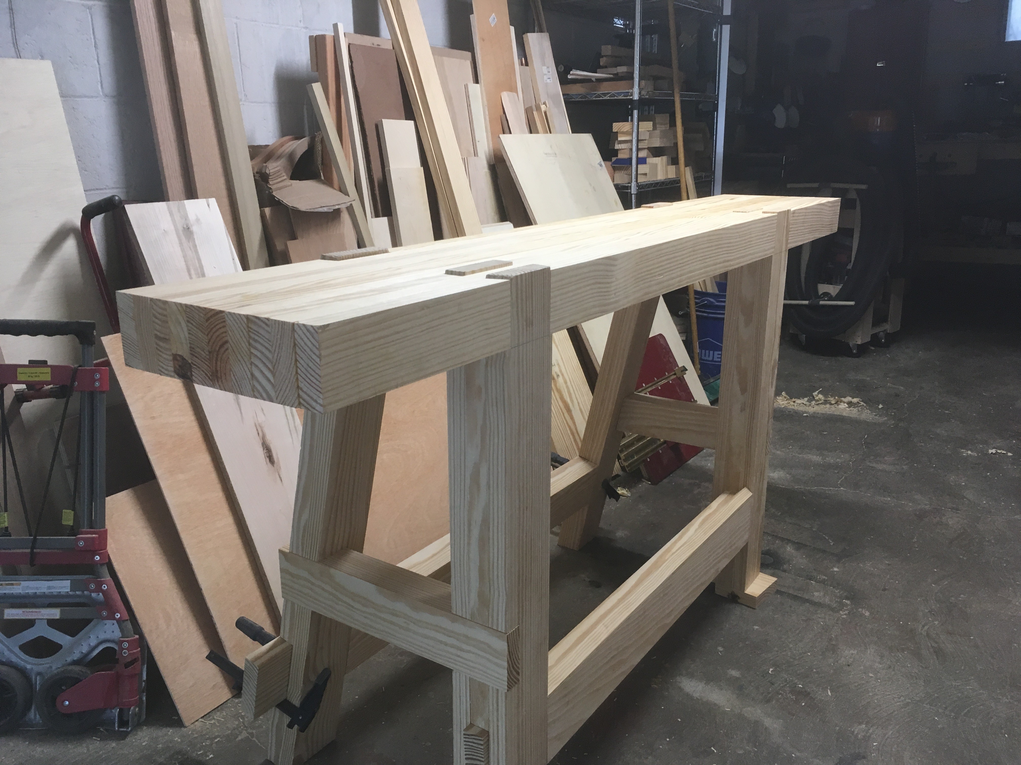
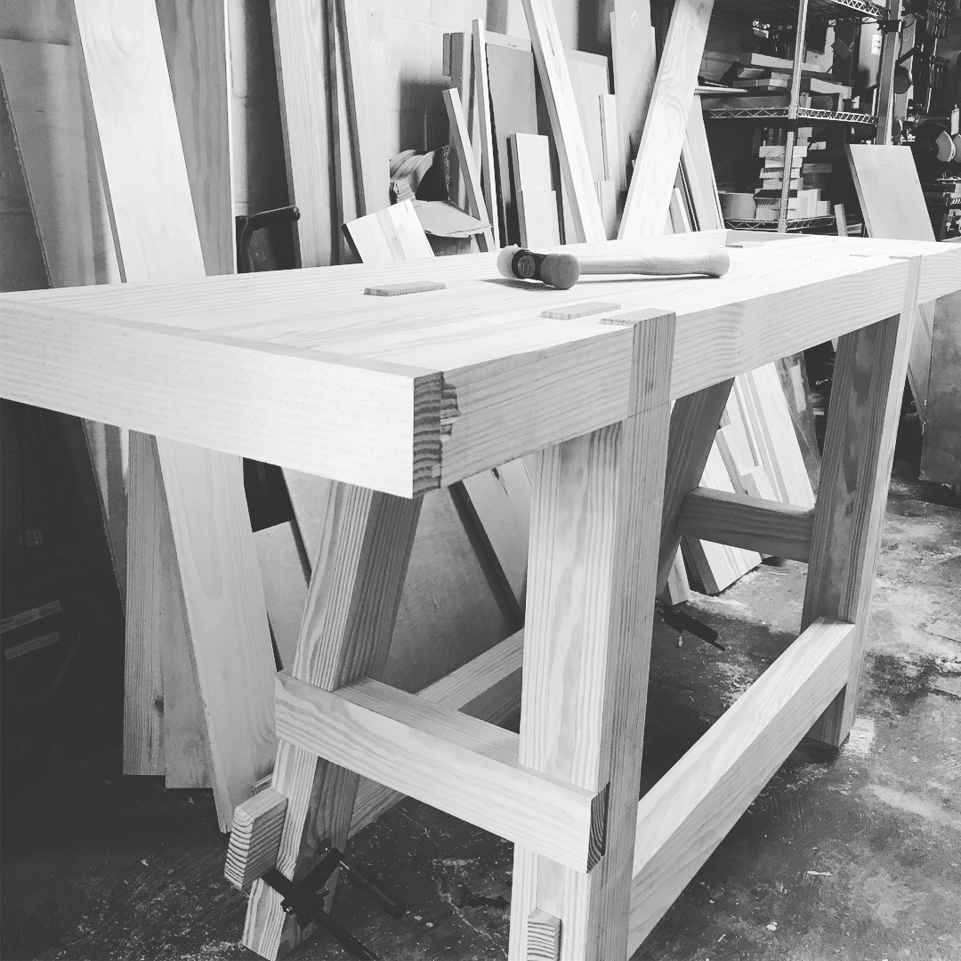
Joining the Parts
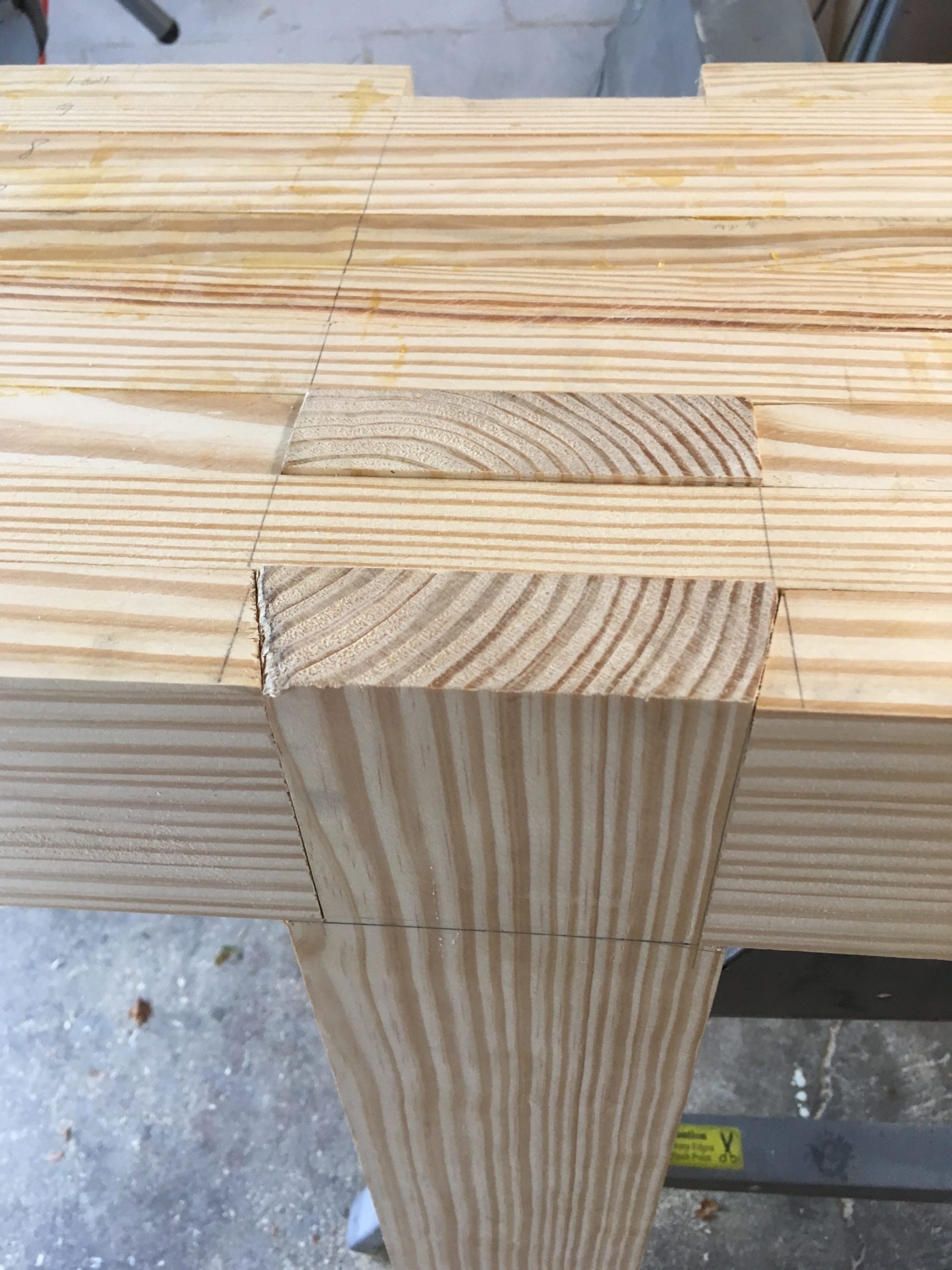
Pre-cutting the joinery before glueup required a bit of patience. However, it turned out well, with a tight and solid fit for the front legs. The rear legs were glued up solid and then had birdsbeaks cut into each leg resulting in 12.5 degrees of splay.
Front Leg Joinery
Front Legs Attached
Birdsbeaks Cut
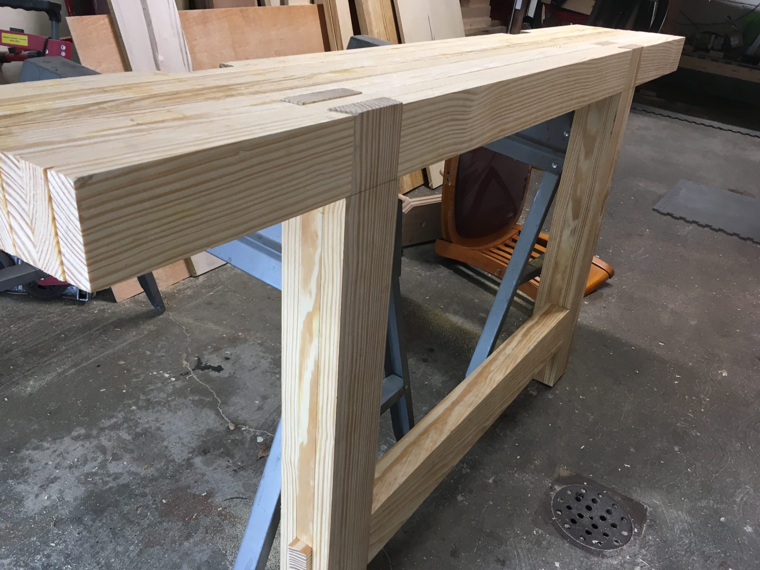
From here it was a matter of gluing up and fitting stretchers to complete the base. The side stretchers were cut using a dado stack on the table saw as well as a miter gauge for the angles in the rear legs. With these angles precisely cut, maintaining the rear splay easy. The top was then run through the thickness planer using the same jointing method as described earlier. With the alignment issues in the top cleaned up, the initial dry fit went perfectly.
Lag bolts were also used to secure the birdsbeaks to the benchtop. The front stretcher was drawbored. Glue for holding the other stretchers to the legs.
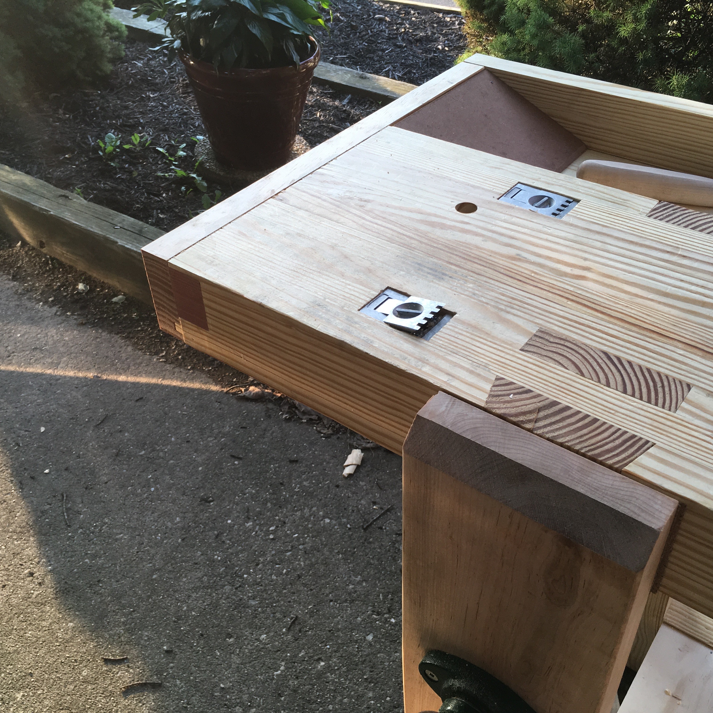
Squaring the Ends
The ends of the bench were then squared using a router and clamped straight edge. To do this, I used a 2 1/2″ inch long 1/2″ straight bit and a 1 1/2″ long 1/2″ flush-trim bit. Since the benchtop is thicker than my longest router bit, the router was passed along the top using the straight edge and straight bit to establish a new square edge. Then the bench was flipped over and the flush-trim bit was used to finish squaring the end. This worked fairly well, except I experienced a bit of blowout on the front leg corner of the bench. This would later have a patch applied. The easier way to do this would be to take the time to develop my handsaw skills to be able to get a square cut (both front to back and top to bottom).
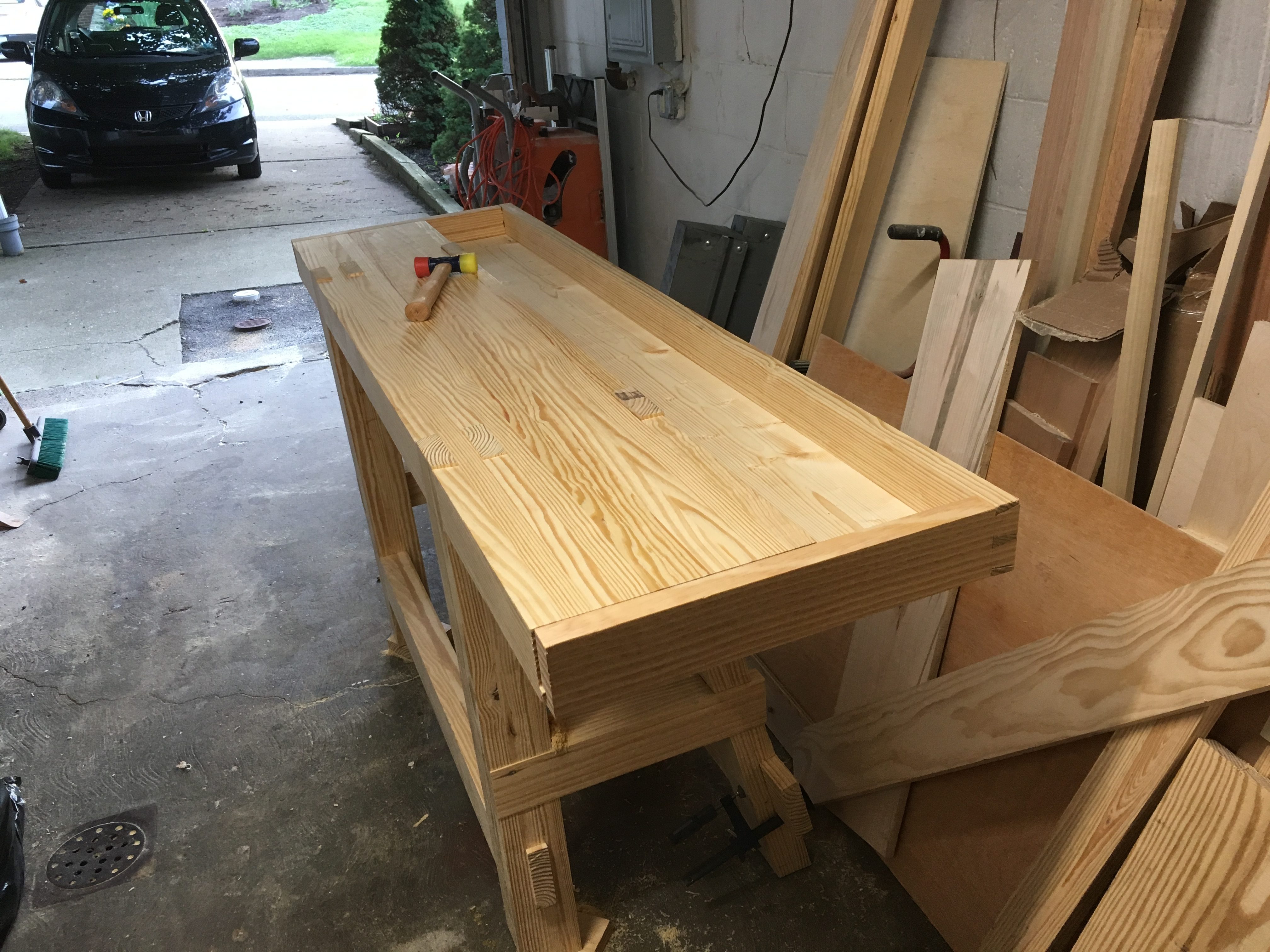
Making the Tool Well
With the ends squared, the next step was to make and fit the tool well. First, I had to cut a 3/8″ x 3/8″ tongue, 3/8″ up from the bottom, on the ends of the bench. To do this, I used a 3/8 rabbet bit from the underside of the bench. Since the top remained over 3 1/4″ thick, the rabbet from the top would still have to come down early 2 1/2″. Rather than risk a blowout, or worse with the powered router, I decided to use my Veritas skew rabbet plane to cut the joint by hand. I was quickly I was able to cut the joint. I kind of wish I had also cut the bottom of the joint by hand.
The tool well frame is dovetailed with grooves that extend all around. A groove was also added to the back of the bench. The grooves on the sides serve double duty. They mate with the tongues on the sides of the bench and hold the bottom of the tool well. I also used lag bolts to secure the tool well to the side of the bench. Cutting the dovetails was fairly straight forward, though, cutting pins in a six-foot long board was a bit of a challenge. I would recommend watching The French Bench-Part II linked above to see the how the pin boards cover the grooves.
Ramps were added at the front and back of the tool well using off-cuts of pine and hardboard. These should help manage dust and shavings.
Vises, Deadmen, and Stops
At this point, I only had a few tasks left. I did a poor job of documenting as I built, so all of these photos are from the finished workbench.
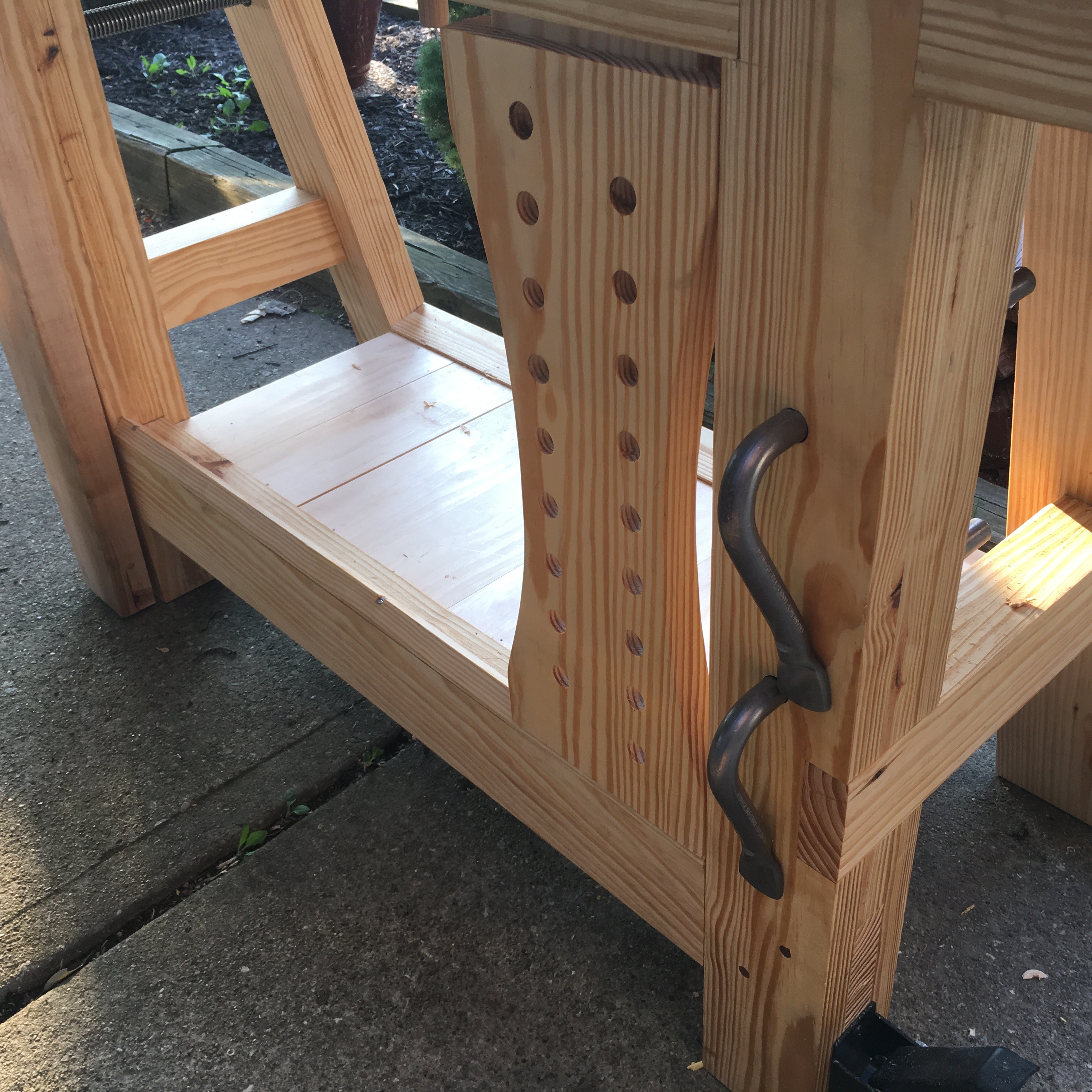
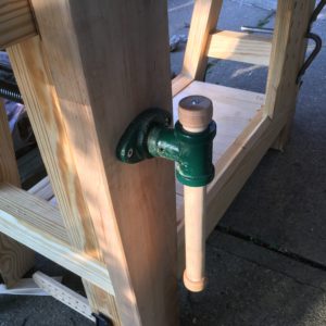
First, I needed to make my sliding deadman. Using the plans from C. Schwarz’ book, I was able to quickly lay out and cut a sliding deadman to fit my bench. I hadn’t pre-cut the track into the front stretcher so I ripped down a 45-degree track from an extra piece of lumber. I then cut notches in three spots along the track to allow a screw to secure the track to the stretcher.
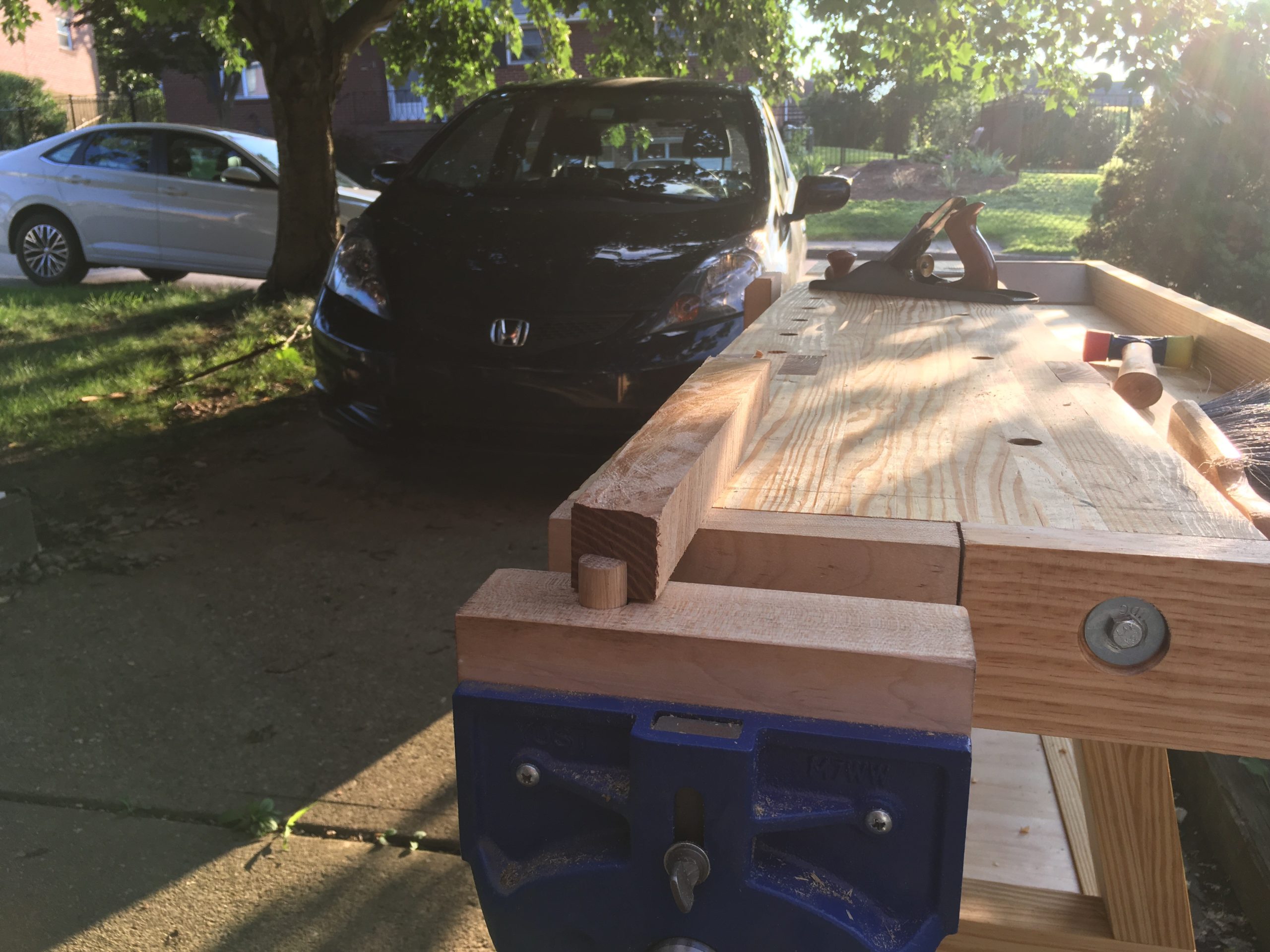
Second, I needed to add face vise. A trip to the lumber yard secured some 8/4 soft maple. This was then jointed and thicknessed to about 1 3/4″. I purchased a vise screw from Lee Valley tools. The flange was fully mortised into the front left leg and 1 1/8″ holes were bored in both the front leg and through the rear leg for the screw. Additionally, I cut a slot in the bottom of the front leg for the parallel guide. A hole was then bored in the maple vise chop. In addition, I had to cut a small mortise into the bottom of the chop for the parallel guide.
Lee Valley Vise Screw
Parallel Guide with Drawbore Pin
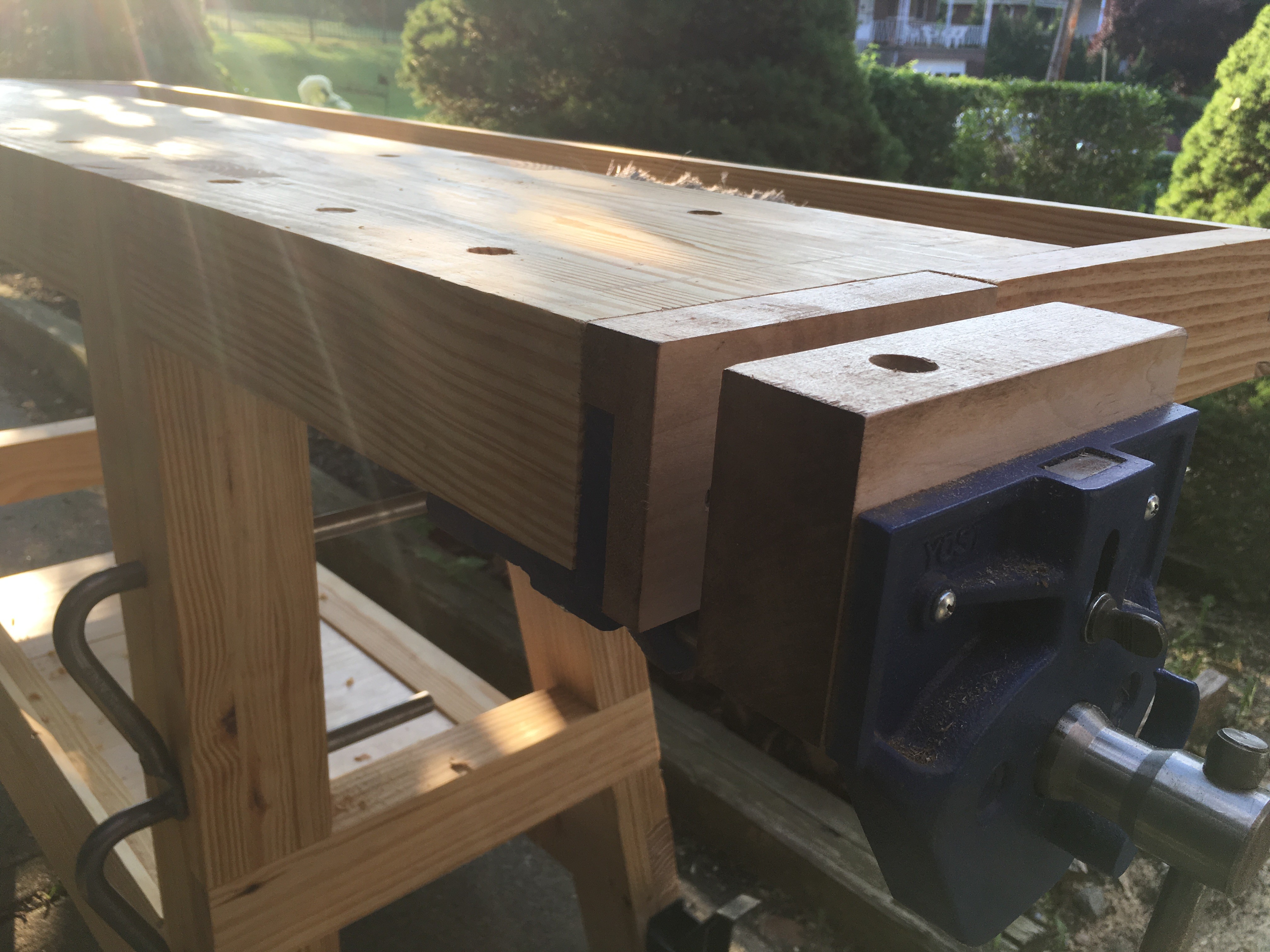
Third, I added a tail vise. Back around Christmas, Amazon ran a sale on Yost vises. I knew that I wanted a quick release vise for my workbench at the time, so I picked up a 7-inch vise on sale (I haven’t seen the prices drop that low since). To attach this vise, I measured the width of the vise jaw.
A section of the tongue was then removed to allow the vise to mount flush to the end of the bench. Fitting the vise had some issues the inside jaw is thicker at the bottom than the top. I used a rasp to sneak up on this angle to get a nice fit. I then cut piece of soft map to use as the inside jaw face. This was thicknessed down to match the tool well side. Since the vise is smaller than the benchtop, a notch was cut out of the inside to get flush with the top. A full thickness piece of soft maple was used for the outside jaw face.
Fourth, I mortised two Lee Valley spring-loaded planing stops into the top of the bench. I bought these a few years ago and never had a bench that could accept them. They aren’t flush with the top as I know I’ll need to flatten the top at some point and don’t want to have to deal with removing them. While they have been fine in use so far, the underside of the casting was designed by someone who clearly didn’t consider the fact that they would have to be installed. There were three to four separate depths, not counting drilling for the cup that holds the spring. I can’t imagine that the materials cost to cast a flat (excepting the spring cup) bottom would break the profit margin on these. Either way, they are in.
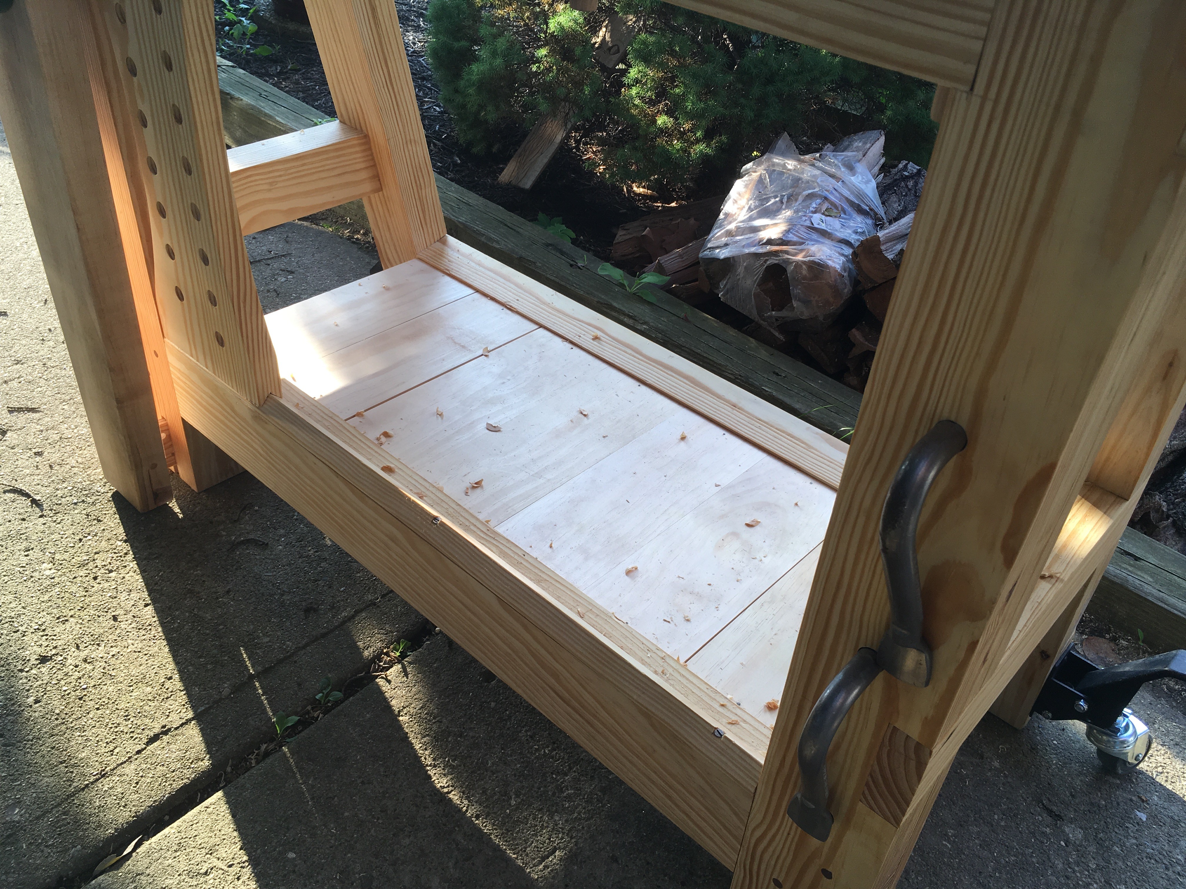
Lower Shelf
I’ve had a shelf below my old workbench since I build it. This has held, at various times, tools, a granite surface plate, tool manuals, sandpaper, and my lathe. In addition to the obvious storage that it provides, the added mass of items on the shelf always helped keep the bench stable when planing.
To add a shelf to the new bench, I first ripped down two shelf supports, including a 12.5-degree bevel on one to match the rear leg splay. The shelf is made up of 7 pieces. Each board has a bevel on one end. The edges are mated with tongue and groove joinery, cut with my Stanley No. 48. The shelf supports are screwed into the stretchers and the boards are nailed to the supports.
This shelf is considerably smaller than my old bench. Since the bench itself is heavier, I’m not worried about losing mass. However, I’ll need to be more organized with what was living under the old bench.
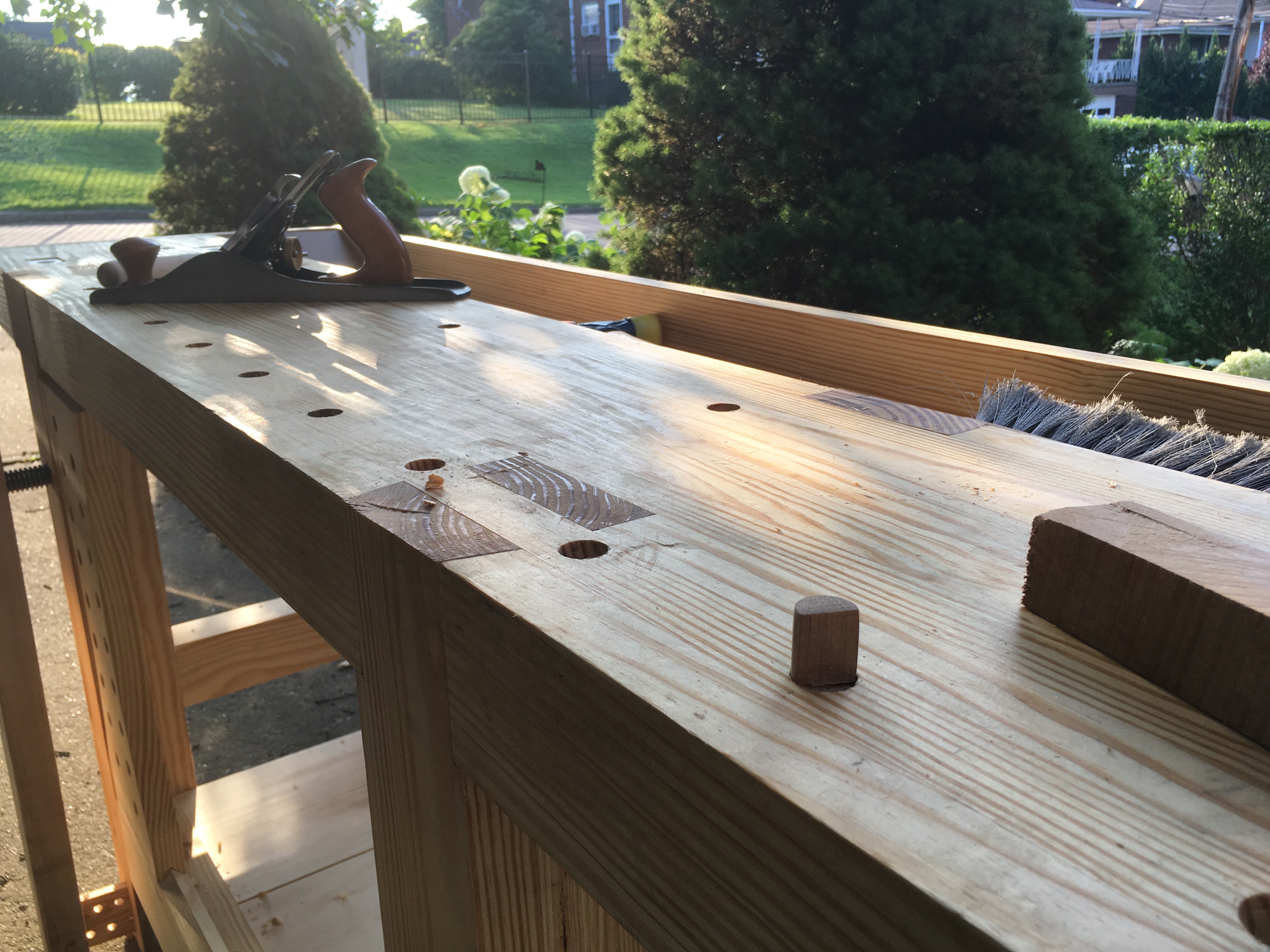
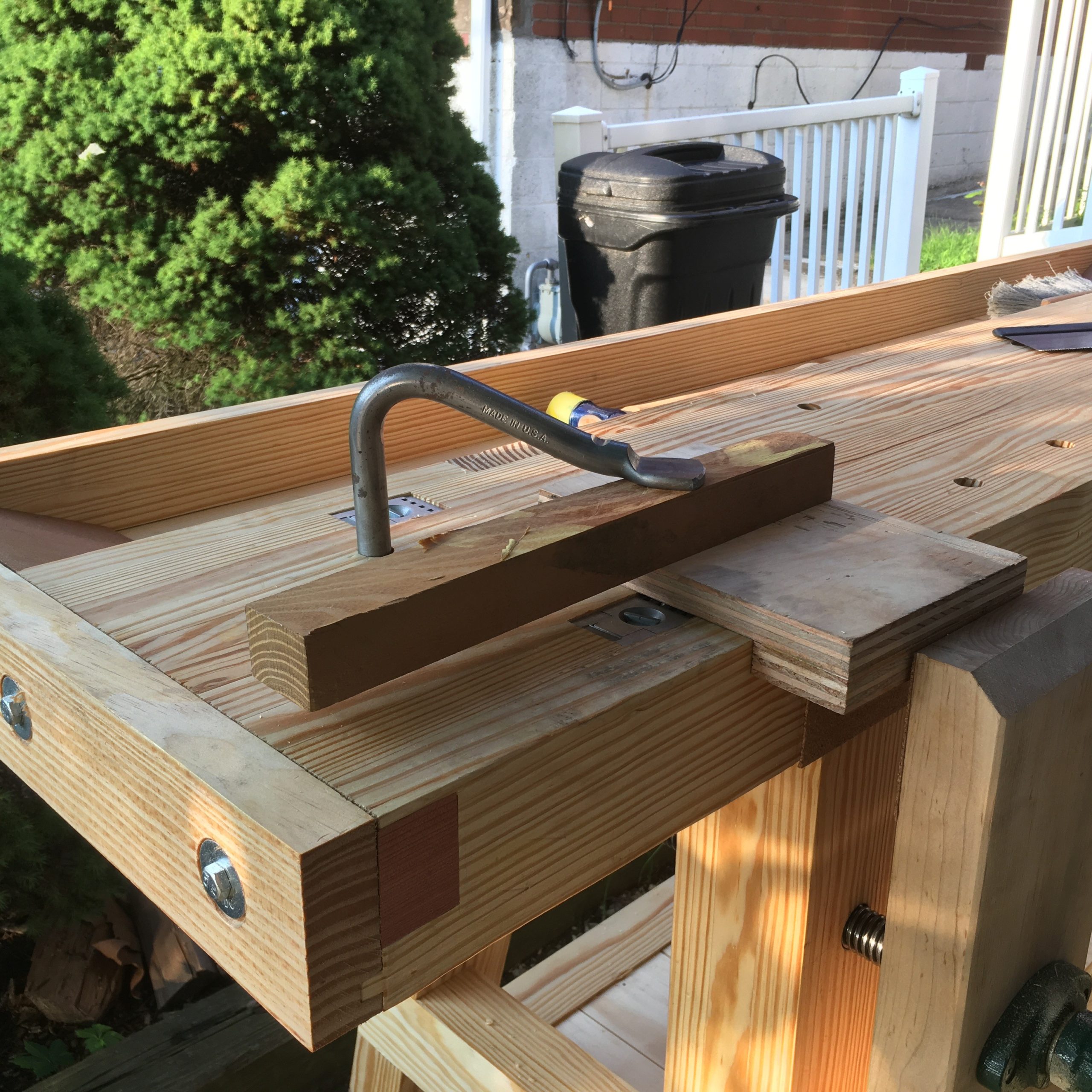
Holes
I added a row of dog holes 2 inches from the front edge of the bench along with a matching hole in the rear jaw of the quick release vise. The front planing stop is also in line with these holes. Additionally, I added four holes for holdfasts about three inches from the rear edge. Finally, one hole was added near the front planing stops.
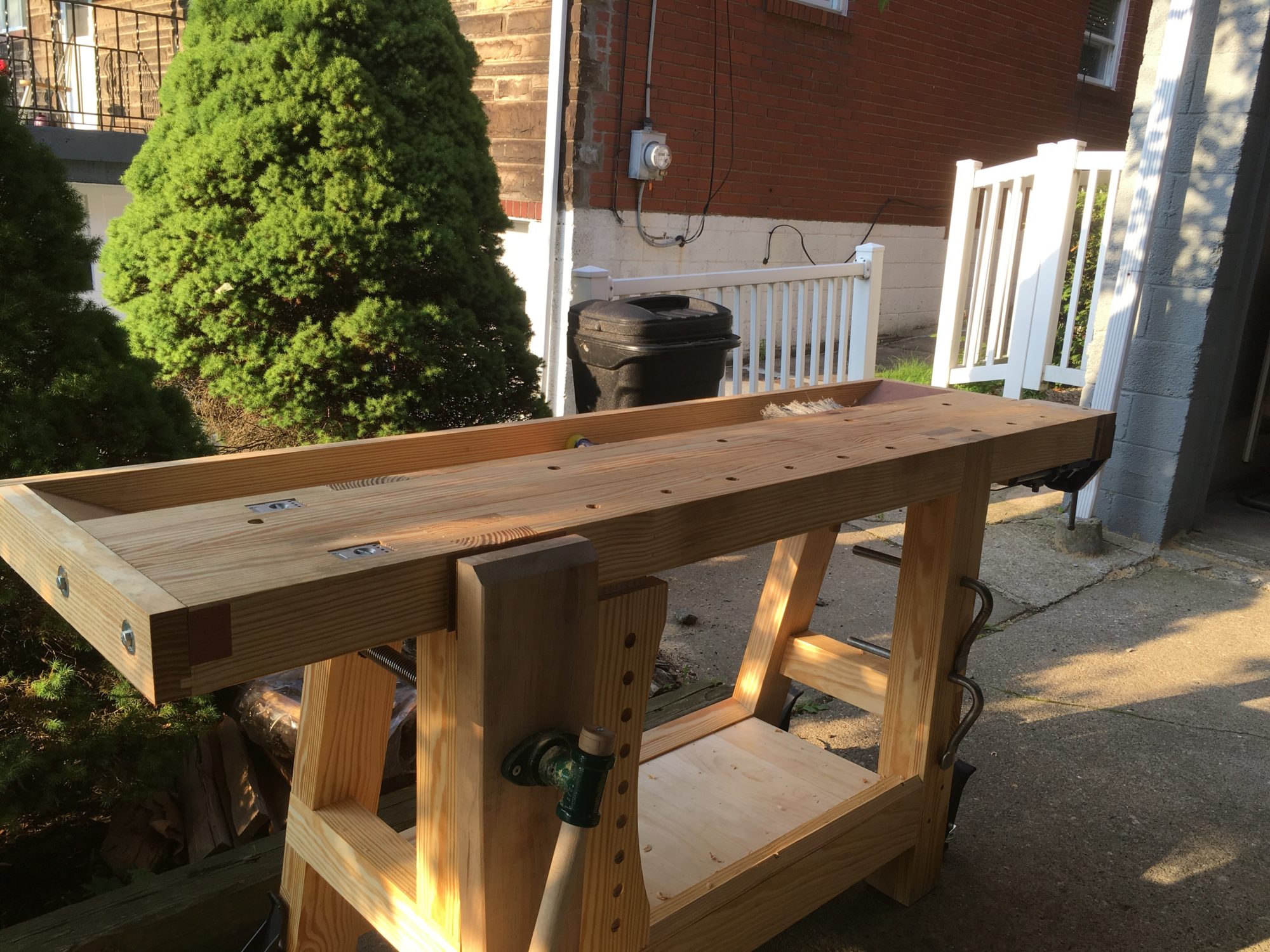
Wrap-up
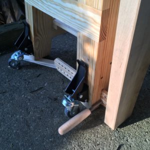
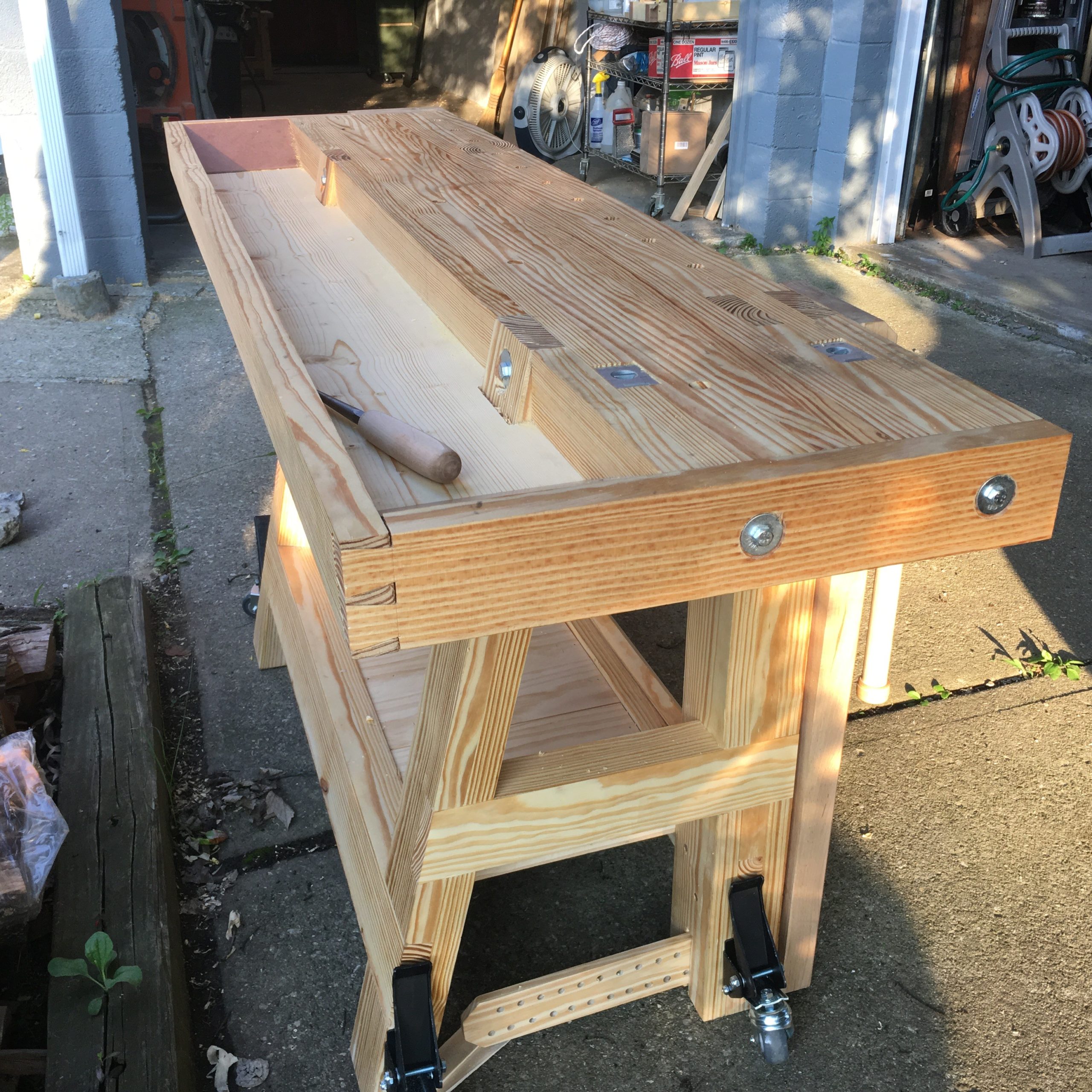
From start to finish, this build tool nearly a month of weekends and evenings. I’m left with a bench that is about 74 inches long, 21 inches deep, and 34 inches high. Due to the weight and my shop size, I added workbench casters to aid in moving the bench around. The bench has already been used for some chores around the shop, including building a new lumber rack.
I definitely can’t wait to put it to use for some new furniture. I’ve included my SketchUp file for anyone that is interested. While I worked from this, there are some changes not reflected in the final build. The placement of holes is not accurate to the final build. Additionally, I changed my plans regarding the jaws on the tail vise, making them flush in the final build.
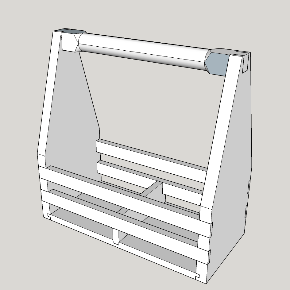
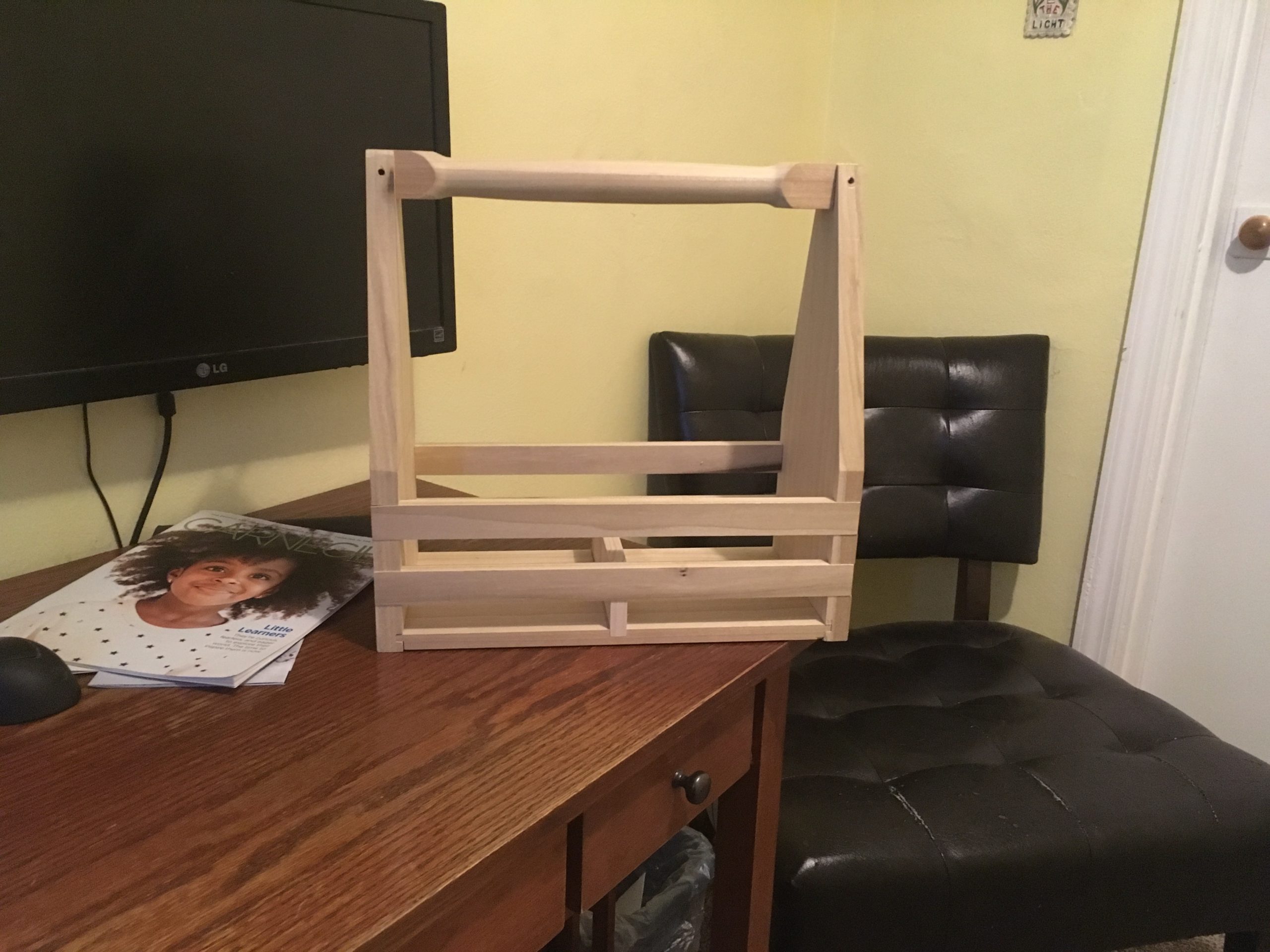
As mentioned in an earlier post, it was suggested to me that I should build a carrier for beer growlers. That design, incorporating a number of different curves, proved to be a time suck in the shop. I may return to it later, after having made proper templates for routing the various curved parts. However, I wanted to simplify the project to make it easier to run a batch of ten to twenty at a time for sale.
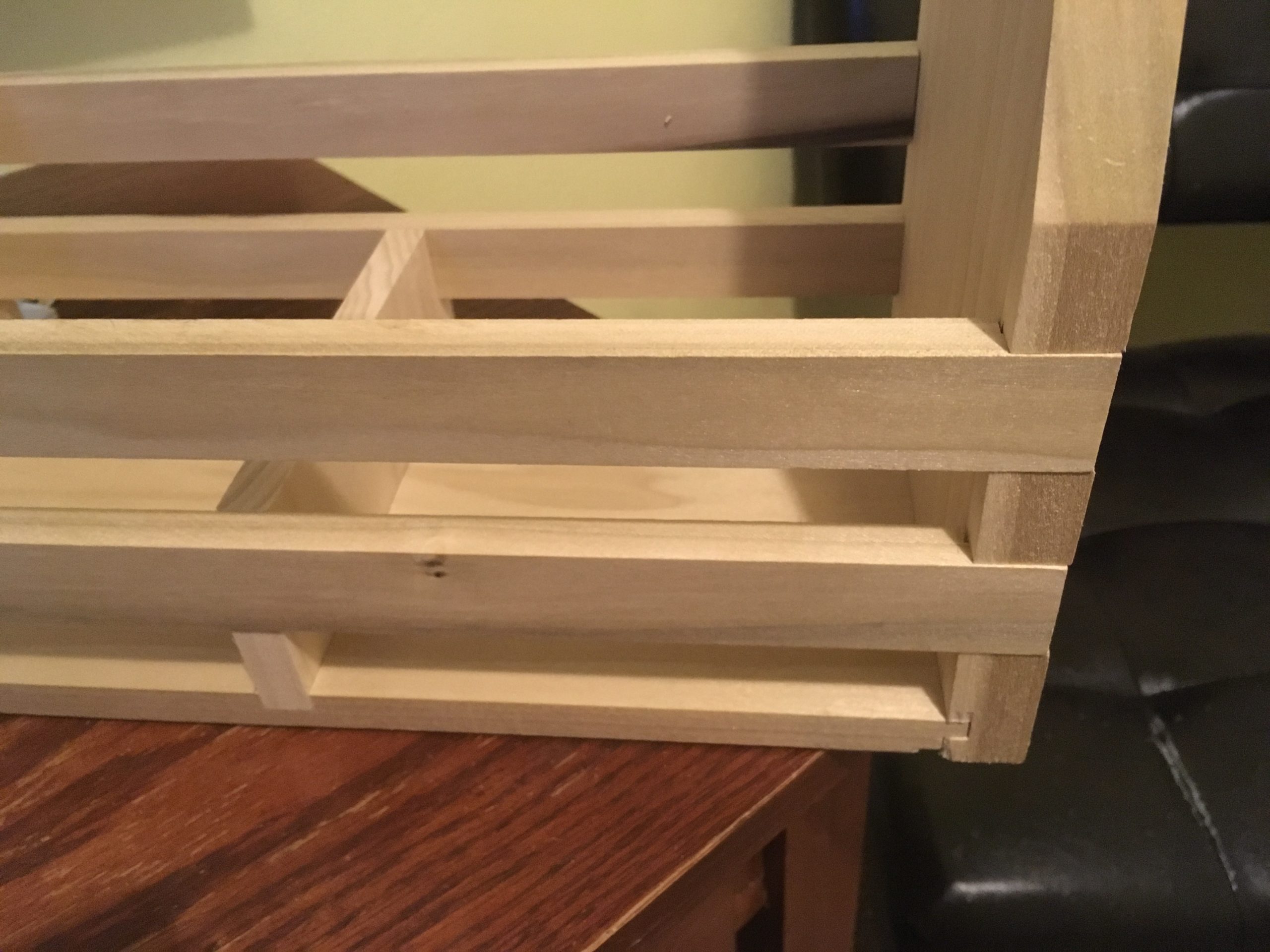
A few design iterations later, and I have just about completed the first prototype. As I’d like to offer this for sale eventually, I have started tracking time in shop to get a feel for how long it will take to be able to make a run of the tote. This also meant tweaking the design to minimize the number setups that are required at the table saw.
I finished glue up on this one earlier today. A final sand and finish is all that is left.
Dry fit, awaiting glueup
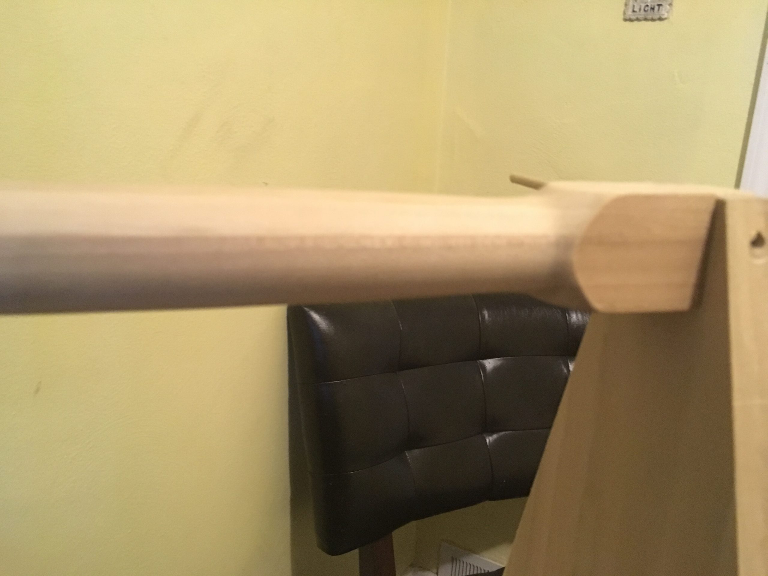
The handle is partly turned. It is much more comfortable to carry than the curved handle of the first design